\n
## Diagram: Optical Setup for Nonlinear Microscopy
### Overview
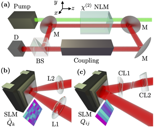
The image depicts three schematic diagrams (a, b, and c) illustrating an optical setup likely used for nonlinear microscopy. The diagrams show the arrangement of optical components and the paths of laser beams (green and red) through the system. The diagrams are labeled with component names and include a coordinate system in diagram (a).
### Components/Axes
* **Diagram (a):**
* **Pump:** Laser source emitting a green beam.
* **χ<sup>(2)</sup> NLM:** Nonlinear Microscopy component.
* **M:** Mirrors (two instances).
* **BS:** Beam Splitter.
* **Coupling:** Coupling component.
* **D:** Detector.
* **Coordinate System:** x, y, and z axes are indicated in the top-right corner.
* **Diagram (b):**
* **SLM:** Spatial Light Modulator labeled as Q<sub>k</sub>. Displays a patterned image.
* **L1 & L2:** Lenses (two instances).
* **Diagram (c):**
* **SLM:** Spatial Light Modulator labeled as Q<sub>ij</sub>. Displays a patterned image.
* **CL1 & CL2:** Cylindrical Lenses (two instances).
### Detailed Analysis or Content Details
**Diagram (a):**
The green laser beam (Pump) enters from the left, passes through the χ<sup>(2)</sup> NLM component, and is reflected by two mirrors (M). A red beam originates from the detector (D), passes through a beam splitter (BS), and is coupled into the system. The coordinate system indicates that the x and y axes are horizontal, and the z axis is vertical.
**Diagram (b):**
A red beam enters from the left, passes through a Spatial Light Modulator (SLM) displaying a patterned image (blue and green squares). The beam is then focused by two lenses (L1 and L2).
**Diagram (c):**
A red beam enters from the left, passes through a Spatial Light Modulator (SLM) displaying a different patterned image (purple and blue gradients). The beam is then shaped by two cylindrical lenses (CL1 and CL2).
### Key Observations
* The diagrams show a progression of optical manipulation. Diagram (a) shows the basic setup, while diagrams (b) and (c) demonstrate how the beam can be shaped using SLMs and lenses.
* The SLMs in diagrams (b) and (c) display different patterns, suggesting that the system can generate various beam profiles.
* The use of cylindrical lenses in diagram (c) indicates that the beam is being shaped into an anisotropic form.
* The color coding (green for the pump laser, red for the signal/detection path) is consistent across all three diagrams.
### Interpretation
The diagrams illustrate a sophisticated optical setup for nonlinear microscopy. The system utilizes a pump laser (green) to induce nonlinear effects in a sample (within the χ<sup>(2)</sup> NLM component). The emitted signal (red) is then manipulated using a beam splitter, spatial light modulators, and lenses to control its spatial properties. The SLMs allow for precise control over the beam profile, enabling techniques such as structured illumination or multi-photon microscopy. The use of cylindrical lenses suggests the ability to create elongated or focused beams. The overall setup is designed to optimize signal collection and enhance imaging resolution. The diagrams suggest a system capable of generating complex beam shapes for advanced microscopy applications. The coordinate system in (a) provides a reference frame for understanding the spatial arrangement of the components. The different patterns on the SLMs in (b) and (c) indicate the system's flexibility in generating different beam profiles for various imaging modalities.