## Optical System Diagram: Experimental Setup
### Overview
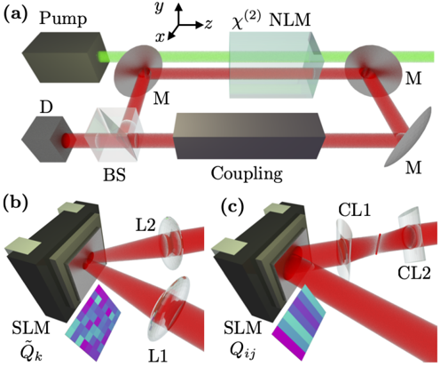
The image depicts a three-part technical diagram of an optical system. Part (a) shows a schematic layout with labeled components and light paths, while parts (b) and (c) provide detailed views of specific subsystems with spatial light modulators (SLMs) and coupling elements.
### Components/Axes
**Part (a):**
- **Labels**: Pump, D, BS, Coupling, M (repeated), χ² NLM
- **Axes**: x (rightward), y (upward), z (out of page)
- **Light Paths**:
- Green line (Pump beam)
- Red lines (signal paths)
- **Key Components**:
- BS: Beam Splitter
- NLM: Nonlinear Mixer (χ²)
- M: Mirrors (three instances)
- D: Detector
**Parts (b) and (c):**
- **SLM**: Spatial Light Modulator (labeled with ~Q_k and Q_ij heatmaps)
- **L1/L2**: Lenses
- **CL1/CL2**: Coupling Lenses
- **Heatmaps**: Color-coded intensity/phase patterns (no numerical values visible)
### Detailed Analysis
**Part (a):**
- Pump beam (green) enters from left, interacts with Beam Splitter (BS), then splits into multiple paths.
- Red paths represent signal beams interacting with:
- Nonlinear Mixer (NLM) for χ² frequency conversion
- Mirrors (M) for beam steering
- Coupling element for beam combination
- Detector (D) positioned at lower-left for signal collection.
**Parts (b) and (c):**
- SLMs modulate light spatially:
- (b) Shows ~Q_k pattern (checkerboard-like)
- (c) Shows Q_ij pattern (gradient stripes)
- Lenses (L1/L2) focus beams before/after SLM
- Coupling elements (CL1/CL2) combine beams with different modulation patterns
### Key Observations
1. **Symmetry**: Mirror configurations (M) in (a) suggest balanced beam steering.
2. **Modulation Diversity**: SLM patterns differ between (b) and (c), implying distinct experimental conditions.
3. **Color Coding**: Green = pump, Red = signal paths, Heatmaps = modulation states.
### Interpretation
This system demonstrates:
1. **Nonlinear Optical Processing**: The χ² NLM enables frequency mixing, critical for applications like parametric amplification.
2. **Adaptive Optics**: SLMs with programmable patterns (Q_k, Q_ij) suggest dynamic control over beam properties.
3. **Beam Management**: Mirrors and couplers optimize path alignment and power distribution.
The absence of numerical data in heatmaps suggests this is a conceptual schematic rather than experimental results. The system appears designed for investigating nonlinear light-matter interactions with programmable spatial modulation.