## Diagram: Cylinder with Flows and Operators
### Overview
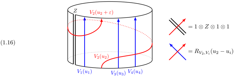
The image depicts a cylindrical diagram with labeled points and flows, along with mathematical expressions representing operators. The cylinder represents a space labeled 'Z'. There are vertical blue arrows and a curved red line indicating flows. To the right are equations defining operators represented by crossing lines.
### Components/Axes
* **Cylinder:** Represents a space labeled "Z" at the top. The cylinder has a vertical cut along its side. The bottom of the cylinder is represented by a dotted line.
* **Vertical Arrows:** Four vertical blue arrows are present, pointing upwards. They originate from points labeled V1(u1), V3(u3), and V4(u4) along the bottom of the cylinder. There are two arrows originating from V3(u3) and V4(u4).
* **Curved Red Line:** A red line starts at the vertical cut, curves along the cylinder, and ends at the top of the cylinder, labeled V2(u2 + ε). Another label, V2(u2), is placed along the red line. The red line is dotted along the top of the cylinder.
* **Operators:** Two equations are shown on the right side of the diagram. The first equation shows two parallel black lines crossing a red arrow. The second equation shows a blue arrow crossing a red arrow.
* **(1.16):** Located on the left side of the diagram.
### Detailed Analysis or Content Details
* **Cylinder Labels:**
* "Z" is at the top of the cylinder.
* "V1(u1)" is at the bottom of the cylinder, at the base of the first blue arrow.
* "V3(u3)" is at the bottom of the cylinder, at the base of the second blue arrow.
* "V4(u4)" is at the bottom of the cylinder, at the base of the third blue arrow.
* "V2(u2)" is along the curved red line.
* "V2(u2 + ε)" is at the top of the cylinder, at the end of the curved red line.
* **Operator Equations:**
* The first equation shows two parallel black lines crossing a red arrow, which is equal to "1 ⊗ Z ⊗ 1 ⊗ 1".
* The second equation shows a blue arrow crossing a red arrow, which is equal to "RV2,Vi(u2 - ui)".
### Key Observations
* The blue arrows represent upward flows from points V1(u1), V3(u3), and V4(u4).
* The red line represents a curved flow from the vertical cut to the top of the cylinder.
* The operator equations define the result of crossing different types of flows.
### Interpretation
The diagram illustrates a system with flows and operators acting on a cylindrical space. The blue arrows represent discrete flows, while the red line represents a continuous flow. The operator equations define how these flows interact with each other. The "Z" label on the cylinder likely represents a specific mathematical space or object. The equations on the right define the result of crossing different types of flows. The diagram likely represents a concept in theoretical physics or mathematics, possibly related to quantum field theory or string theory.