## Diagram: Neural Logic Machine (NLM) Architecture
### Overview
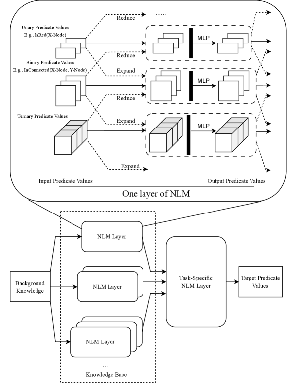
The diagram illustrates a multi-layered Neural Logic Machine (NLM) architecture designed to process predicate values (unary, binary, ternary) through reduction/expansion operations, integrate background knowledge, and produce task-specific target predicate values. The flow involves multiple NLM layers, MLPs (Multi-Layer Perceptrons), and hierarchical knowledge integration.
### Components/Axes
1. **Top Section: One Layer of NLM**
- **Input Predicate Values**:
- Unary (e.g., `IsRed(X-Node)`)
- Binary (e.g., `InConnected(X-Node, Y-Node)`)
- Ternary (e.g., `InConnected(X-Node, Y-Node, Z-Node)`)
- **Operations**:
- **Reduce**: Applied to unary and binary predicates (dashed arrows).
- **Expand**: Applied to ternary predicates (dashed arrows).
- **MLP**: Processes reduced/expanded predicates (solid arrows).
- **Output Predicate Values**: Resulting from MLP transformations.
2. **Bottom Section: Full Architecture**
- **Background Knowledge**: Feeds into the base NLM layer.
- **NLM Layers**: Stacked vertically (labeled "NLM Layer" with ellipsis for additional layers).
- **Task-Specific NLM Layer**: Final layer integrating all prior outputs.
- **Target Predicate Values**: Final output of the architecture.
### Detailed Analysis
- **Predicate Value Flow**:
- Unary and binary predicates are reduced (simplified) before MLP processing.
- Ternary predicates are expanded (decomposed) before MLP processing.
- MLPs act as transformation modules between predicate layers.
- **Knowledge Integration**:
- Background knowledge is injected at the base NLM layer, influencing subsequent layers.
- Task-specific logic is encapsulated in the final NLM layer.
### Key Observations
- **Hierarchical Processing**: The architecture uses layered NLM modules to progressively refine predicate values.
- **Dynamic Operations**: Reduction/expansion operations adapt based on predicate arity (unary/binary vs. ternary).
- **MLP Role**: MLPs serve as non-linear transformers between predicate layers, enabling complex feature learning.
### Interpretation
The diagram demonstrates a modular approach to predicate-based reasoning, where:
1. **Reduction/Expansion** tailors input complexity for efficient processing.
2. **Background Knowledge** provides foundational context, enhancing the model’s ability to generalize.
3. **Task-Specific Layers** allow customization for downstream applications (e.g., question answering, logical inference).
The use of MLPs between layers suggests a focus on capturing non-linear relationships in predicate interactions. The architecture’s design implies a balance between symbolic logic (predicates) and neural learning (MLPs), enabling hybrid reasoning capabilities.
**Note**: No numerical data or trends are present in the diagram; it focuses on structural and procedural relationships.