## Flowchart Diagram: System Interaction Model
### Overview
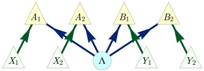
The diagram illustrates a hierarchical system with a central node (Λ) connected to four intermediate nodes (A1, A2, B1, B2), which in turn connect to terminal nodes (X1, X2, Y1, Y2). Arrows indicate directional relationships, with color-coded distinctions between direct and indirect influences.
### Components/Axes
- **Nodes**:
- Central node: Λ (light blue circle)
- Intermediate nodes: A1, A2, B1, B2 (yellow triangles)
- Terminal nodes: X1, X2, Y1, Y2 (gray triangles)
- **Arrows**:
- Green arrows: Labeled "Direct Influence" in legend
- Blue arrows: Labeled "Indirect Influence" in legend
- **Legend**: Positioned at bottom-right corner, explicitly mapping colors to influence types.
### Detailed Analysis
1. **Central Node (Λ)**:
- Receives **blue arrows** (indirect influence) from A1, A2, B1, and B2.
- Distributes **blue arrows** (indirect influence) to A1, A2, B1, and B2.
2. **Intermediate Nodes**:
- **A1/A2**:
- Receive blue arrows from Λ (indirect influence).
- Distribute green arrows (direct influence) to X1 and X2, respectively.
- **B1/B2**:
- Receive blue arrows from Λ (indirect influence).
- Distribute green arrows (direct influence) to Y1 and Y2, respectively.
3. **Terminal Nodes**:
- X1, X2: Receive green arrows from A1 and A2 (direct influence).
- Y1, Y2: Receive green arrows from B1 and B2 (direct influence).
### Key Observations
- **Color Consistency**: All green arrows align with the "Direct Influence" legend label; blue arrows match "Indirect Influence."
- **Flow Direction**:
- Λ acts as a hub, mediating interactions between intermediate and terminal nodes.
- No feedback loops or bidirectional relationships are depicted.
- **Symmetry**: The diagram is balanced, with A1/A2/X1/X2 and B1/B2/Y1/Y2 forming mirrored subgraphs.
### Interpretation
The diagram represents a **two-path influence model** where:
1. **Λ** serves as a central coordinator, indirectly affecting all terminal nodes through intermediate nodes (A1/A2/B1/B2).
2. **Direct Influence** (green arrows) originates exclusively from intermediate nodes to terminal nodes, suggesting localized control or decision-making at the A/B level.
3. **Indirect Influence** (blue arrows) flows bidirectionally between Λ and intermediate nodes, implying Λ’s role in modulating or regulating the system’s behavior without direct intervention at the terminal level.
This structure could model organizational hierarchies, neural networks, or decision-making frameworks where central authority (Λ) delegates influence through intermediary layers (A/B nodes) to execute localized actions (X/Y nodes). The absence of feedback loops suggests a linear, top-down operational model.