TECHNICAL ASSET FINGERPRINT
aa6d4ad699d62ee0d3966ca5
Click to view fullscreen
Press ESC or click to close
FOUND IN PAPERS
EXPERT: healer-alpha-free VERSION 1
RUNTIME: free/openrouter/healer-alpha
INTEL_VERIFIED
## Technical Diagram Composite: 8T4R Unit-Cell and Array Architecture
### Overview
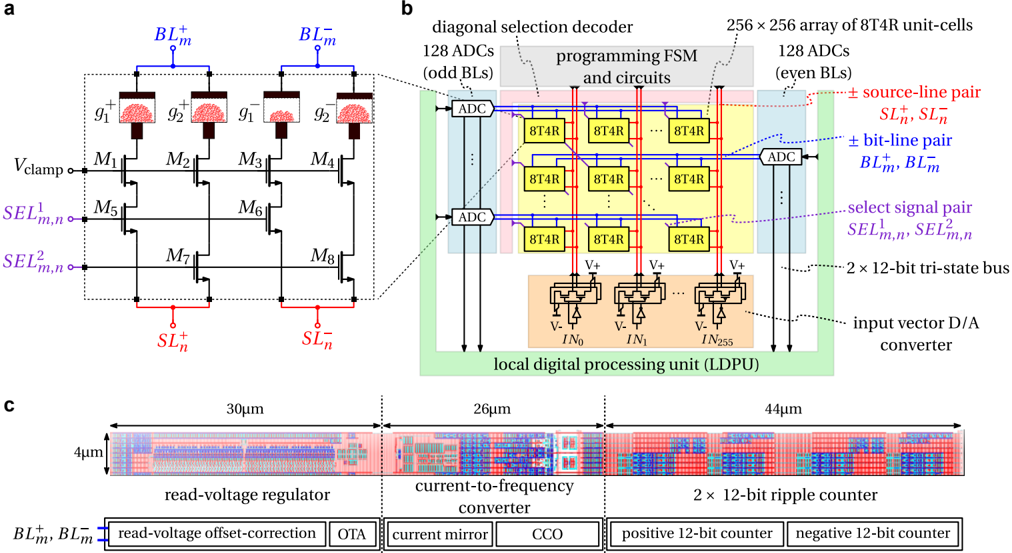
The image is a composite of three technical diagrams (labeled a, b, and c) detailing the circuit design, system architecture, and physical layout of a memory/processing array based on an 8T4R (8-transistor, 4-resistor) unit-cell. The diagrams progress from a transistor-level schematic to a system-level block diagram and finally to a physical layout view.
### Components/Axes
The image contains three distinct panels:
* **Panel a:** A circuit schematic of a single 8T4R unit-cell.
* **Panel b:** A block diagram of a 256x256 array of these unit-cells and its supporting circuitry.
* **Panel c:** A physical layout diagram of a key circuit block with dimensional annotations.
### Detailed Analysis
#### **Panel a: 8T4R Unit-Cell Schematic**
* **Type:** Circuit Schematic.
* **Components & Labels:**
* **Resistive Elements:** Four memristor-like devices labeled `g₁⁺`, `g₂⁺`, `g₁⁻`, `g₂⁻`. They are depicted as red rectangles with a wavy internal pattern.
* **Transistors:** Eight NMOS transistors labeled `M₁` through `M₈`.
* **Voltage/Signal Lines:**
* `Vclamp`: A clamping voltage input connected to the gates of `M₁` and `M₃`.
* `SEL¹ₘ,ₙ` and `SEL²ₘ,ₙ`: Select signal lines (purple) connected to the gates of `M₅`/`M₆` and `M₇`/`M₈` respectively.
* `BL⁺ₘ` and `BL⁻ₘ`: Positive and negative bit-line pairs (blue) connected to the top of the resistive elements.
* `SL⁺ₙ` and `SL⁻ₙ`: Positive and negative source-line pairs (red) connected to the bottom of the transistor network.
* **Structure:** The circuit is arranged in two symmetrical vertical branches. The left branch contains `g₁⁺`, `g₂⁺`, `M₁`, `M₂`, `M₅`, `M₇`. The right branch contains `g₁⁻`, `g₂⁻`, `M₃`, `M₄`, `M₆`, `M₈`. The `Vclamp` and `SEL` signals control the connection of the resistive elements to the source lines.
#### **Panel b: 256x256 Array and System Architecture**
* **Type:** System Block Diagram.
* **Components & Labels (Spatially Grounded):**
* **Top Region:**
* `diagonal selection decoder` (text, top-left).
* `programming FSM and circuits` (text, top-center, within a grey box).
* **Main Array Region (Center):**
* A grid labeled `256 x 256 array of 8T4R unit-cells` (text, top-right).
* The grid is composed of yellow squares, each labeled `8T4R`.
* **Left Side:** A column of blocks labeled `128 ADCs (odd BLs)`.
* **Right Side:** A column of blocks labeled `128 ADCs (even BLs)`.
* **Bottom Region:**
* A large green block labeled `local digital processing unit (LDPU)`.
* Within the LDPU: Three blocks labeled `V+`, `V-`, and `IN₀`, `IN₁`, ..., `IN₂₅₅`, connected to a `2 x 12-bit tri-state bus` and an `input vector D/A converter`.
* **Legend (Right Side, Spatially Grounded):**
* **Red Text/Lines:** `± source-line pair SL⁺ₙ, SL⁻ₙ`. These lines run vertically through the array.
* **Blue Text/Lines:** `± bit-line pair BL⁺ₘ, BL⁻ₘ`. These lines run horizontally through the array.
* **Purple Text/Lines:** `select signal pair SEL¹ₘ,ₙ, SEL²ₘ,ₙ`. These lines run diagonally from the top-left decoder.
* **Flow & Relationships:** The diagram shows a hierarchical structure. The diagonal decoder and programming FSM control the 256x256 core array. The array is read by 128 ADCs on each side (for odd and even bit-lines). The processed data is handled by the LDPU at the bottom, which includes digital-to-analog conversion for input vectors.
#### **Panel c: Physical Layout Diagram**
* **Type:** Layout Diagram with Dimensions.
* **Components & Labels:**
* **Top Dimension Line:** Spans the entire width with three segments: `30µm`, `26µm`, `44µm`.
* **Left Dimension:** `4µm` indicating the height of the layout.
* **Main Layout Blocks (from left to right):**
* `read-voltage regulator` (under the 30µm segment).
* `current-to-frequency converter` (under the 26µm segment).
* `2 x 12-bit ripple counter` (under the 44µm segment).
* **Sub-Block Diagram (Bottom):** A simplified block diagram corresponding to the layout above.
* Input: `BL⁺ₘ, BL⁻ₘ`.
* Blocks: `read-voltage offset-correction`, `OTA`, `current mirror`, `CCO`, `positive 12-bit counter`, `negative 12-bit counter`.
* **Spatial Grounding:** The layout is a long, thin rectangle (4µm tall). The functional blocks are arranged linearly from left to right, matching the dimensional segments above them.
### Key Observations
1. **Symmetry and Differential Design:** The unit-cell (a) and the array bit/source lines (b) use fully differential signaling (`+`/`-` pairs), which is common for noise immunity in sensitive memory/processing arrays.
2. **Hierarchical Integration:** The diagrams show a clear hierarchy from device (a) to array subsystem (b) to a specific circuit's physical implementation (c).
3. **Mixed-Signal Design:** The system integrates analog components (memristors, ADCs, OTAs, regulators) with digital control (FSM, decoders, counters, LDPU).
4. **Scalability:** The 256x256 array specification indicates a focus on creating a scalable core for computation-in-memory or analog processing applications.
5. **Precision Layout:** The 4µm height and specific length allocations (30µm, 26µm, 44µm) in panel (c) highlight the careful physical design required for analog blocks like the read-voltage regulator and current-to-frequency converter.
### Interpretation
This set of diagrams describes a complete compute-in-memory or analog signal processing subsystem. The **8T4R cell** is the fundamental storage/processing element, likely using its resistive states (`g`) to perform analog multiplication or synaptic weighting. The **256x256 array** forms a crossbar where these operations can be performed in parallel on input vectors (provided by the LDPU's D/A converter). The **ADCs** convert the analog results (e.g., currents summed on the bit-lines) back to digital for further processing by the LDPU.
The **layout in panel (c)** focuses on a critical analog front-end circuit—the read-voltage regulator and current-to-frequency converter. This block is essential for accurately reading the state of the unit-cells and converting that analog current into a digital frequency count (via the ripple counters), which is a common technique for high-precision, low-power analog-to-digital conversion in such systems.
**Overall Purpose:** The system is designed for efficient, parallel analog computation, potentially for neural network inference, signal processing, or other matrix-vector multiplication tasks, where the memory array itself performs the computation, reducing data movement bottlenecks. The detailed layout underscores the importance of analog circuit precision in realizing the theoretical benefits of the architecture.
DECODING INTELLIGENCE...