## Diagram: Grid Map with Obstacles and Labeled Points
### Overview
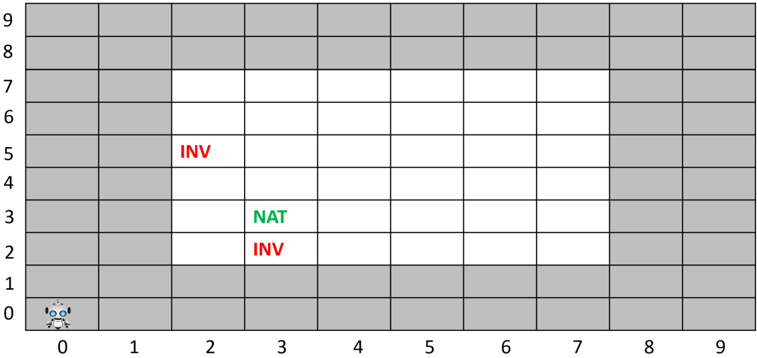
This image displays a 2D grid map, 10 units by 10 units, representing an environment for navigation. The grid cells are either grey, indicating an obstacle or impassable area, or white, indicating an open or traversable area. A small robot icon is positioned at the starting point. Within the open area, specific cells are marked with text labels "INV" (in red) and "NAT" (in green), likely denoting points of interest or different types of locations.
### Components/Axes
The image is structured as a Cartesian grid with clearly marked axes:
* **X-axis (Horizontal):** Labeled with integers from 0 to 9, increasing from left to right, positioned along the bottom edge of the grid.
* **Y-axis (Vertical):** Labeled with integers from 0 to 9, increasing from bottom to top, positioned along the left edge of the grid.
* **Grid Cells:** The map consists of 100 individual cells, each identifiable by its (X, Y) coordinates.
* **Grey Cells:** These cells represent obstacles or boundaries. They form a perimeter around a central open area.
* **White Cells:** These cells represent the traversable path or open space within the environment.
* **Robot Icon:** A small, light blue and white robot character, depicted with large eyes and antennae, is located in the bottom-left corner of the grid.
* **Text Labels:**
* **"INV" (Red Text):** Appears twice within the white cells.
* **"NAT" (Green Text):** Appears once within the white cells.
### Detailed Analysis
The grid is a 10x10 matrix of cells, indexed from 0 to 9 on both axes.
**Grid Structure:**
* **Obstacle Cells (Grey):**
* All cells in rows Y=0 and Y=1 are grey.
* All cells in rows Y=8 and Y=9 are grey.
* All cells in columns X=0 and X=1 are grey, for rows Y=2 through Y=7.
* All cells in columns X=8 and X=9 are grey, for rows Y=2 through Y=7.
* This configuration creates a thick border of grey cells around the central region.
* **Open Cells (White):**
* The central area of white cells forms a rectangle. These cells span X-coordinates from 2 to 7 (inclusive) and Y-coordinates from 2 to 7 (inclusive).
* Specifically, the white cells are located at (X, Y) where 2 ≤ X ≤ 7 and 2 ≤ Y ≤ 7. This constitutes a 6x6 block of 36 traversable cells.
**Specific Elements and Their Positions:**
* **Robot Icon:** The robot is positioned in the cell at coordinates (0,0), which is a grey cell in the bottom-left corner of the grid.
* **Text Labels:**
* The red text "INV" is located in the white cell at coordinates (2,5).
* The green text "NAT" is located in the white cell at coordinates (3,3).
* Another instance of the red text "INV" is located in the white cell at coordinates (2,2).
### Key Observations
* The grid clearly delineates a confined, rectangular traversable area (white cells) surrounded by impassable obstacles (grey cells).
* The robot starts outside the main traversable area, in a grey cell, suggesting it needs to navigate into the white region.
* There are three distinct labeled points within the traversable area, two marked "INV" in red and one marked "NAT" in green. The color coding suggests different categories or properties for these points.
* The "INV" labels are positioned at the leftmost edge of the white area (X=2), while "NAT" is slightly more central (X=3).
### Interpretation
This grid map likely represents an environment for a pathfinding or reinforcement learning problem.
* The **robot** at (0,0) is the agent, and its initial position in a grey cell implies it might need to find an entry point into the main playable area, or perhaps (0,0) is a designated starting zone that is technically an "obstacle" for general movement but allows initial placement.
* The **grey cells** are clearly obstacles, defining the boundaries and structure of the environment. The **white cells** are the navigable space where the agent can move.
* The **"INV" (red)** and **"NAT" (green)** labels suggest different types of locations or objectives within the environment.
* "NAT" (green) could represent a "Natural" target, a "Navigation" point, or a desirable goal for the robot to reach. Its green color often signifies positive or permissible states.
* "INV" (red) could represent "Invalid" locations, "Inaccessible" points (despite being in a white cell, perhaps they have a negative consequence), "Inventory" collection points, or areas to avoid. Its red color often signifies negative or warning states.
* The task for the robot could involve navigating from its starting position, entering the white area, and then interacting with these labeled points, perhaps reaching "NAT" while avoiding or performing a specific action at "INV" locations. This setup is typical for demonstrating or testing AI navigation algorithms in a constrained environment.