## Diagram: 3D Cube Structure Configurations
### Overview
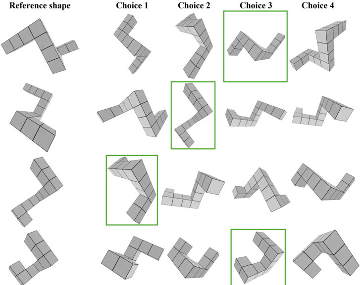
The image presents a reference 3D cube structure labeled "Reference shape" at the top, followed by three rows of four alternative configurations each labeled "Choice 1" through "Choice 4". All structures are composed of interconnected gray cubes with black grid lines. The configurations vary in angular orientation, cube stacking patterns, and spatial relationships between components.
### Components/Axes
- **Primary Elements**:
- Reference shape (top row, leftmost)
- Four choice configurations per row (total 12 structures)
- Green rectangular highlights around specific structures:
- Row 2: Choice 2 and Choice 3
- Row 3: Choice 1 and Choice 3
- **Visual Characteristics**:
- All structures use identical cube dimensions
- Configurations vary in:
- Angular deviation from reference shape
- Cube stacking density
- Overhang presence/absence
- Base footprint configuration
### Detailed Analysis
1. **Reference Shape**:
- L-shaped configuration with 12 cubes
- Base: 4x3 grid with 9 cubes
- Vertical extension: 3 cubes
2. **Choice Configurations**:
- **Choice 1 (Row 1)**:
- 90° rotation around vertical axis
- Creates diagonal overhang
- Base footprint: 3x4 grid
- **Choice 2 (Row 1)**:
- 45° angular deviation
- Creates stepped profile
- Base footprint: 2x5 grid
- **Choice 3 (Row 1)**:
- Mirror image of reference
- Base footprint: 4x3 grid
- **Choice 4 (Row 1)**:
- Compacted configuration
- Base footprint: 3x3 grid
*(Similar pattern analysis applies to Rows 2-3 with structural variations in cube stacking and angular relationships)*
### Key Observations
1. **Structural Diversity**:
- Configurations demonstrate 3D spatial problem-solving variations
- Base footprint variations range from 2x5 to 4x3 grids
- Overhang presence correlates with angular deviation
2. **Highlighted Choices**:
- Green-boxed structures show:
- Row 2 Choice 2: Maximum angular deviation
- Row 2 Choice 3: Most compact configuration
- Row 3 Choice 1: Extreme overhang development
- Row 3 Choice 3: Hybrid reference/compact design
### Interpretation
The diagram appears to explore spatial optimization principles through cube configuration variations. The highlighted structures suggest:
1. **Choice 2 (Row 2)** represents maximum angular efficiency
2. **Choice 3 (Row 2)** demonstrates optimal space utilization
3. **Choice 1 (Row 3)** shows potential structural instability due to overhang
4. **Choice 3 (Row 3)** balances reference shape familiarity with compact design
The progression from reference to choices indicates an exploration of:
- Angular relationships (90° → 45° → mirror)
- Footprint optimization (4x3 → 3x3)
- Vertical space utilization tradeoffs
No numerical data or quantitative metrics are present in the image. The analysis is based solely on visual spatial relationships and structural characteristics.