## Diagram: PowerPC 450 Simulator Workflow
### Overview
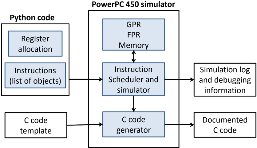
The image is a block diagram illustrating the workflow of a PowerPC 450 simulator. It shows the interaction between Python code, the PowerPC 450 simulator, and the generation of C code, along with simulation logs.
### Components/Axes
* **Title:** PowerPC 450 simulator
* **Left Block:** Python code
* Sub-blocks:
* Register allocation
* Instructions (list of objects)
* C code template
* **Center Block:** PowerPC 450 simulator
* Sub-blocks:
* GPR, FPR, Memory (with bidirectional arrow to Instruction Scheduler)
* Instruction Scheduler and simulator
* C code generator
* **Right Block:** Output
* Sub-blocks:
* Simulation log and debugging information
* Documented C code
* **Arrows:** Indicate the flow of data and control between the blocks.
### Detailed Analysis
* **Python code:** This section represents the input to the simulator. It includes register allocation information, a list of instructions (as objects), and a C code template.
* **PowerPC 450 simulator:** This is the core of the system. It consists of:
* GPR, FPR, Memory: General Purpose Registers, Floating Point Registers, and Memory. These components interact bidirectionally with the Instruction Scheduler.
* Instruction Scheduler and simulator: This component schedules and simulates the instructions.
* C code generator: This component generates C code based on the simulation.
* **Output:** The output of the simulation includes:
* Simulation log and debugging information: Logs and debugging data generated during the simulation.
* Documented C code: The final C code, presumably documented for further use.
The arrows indicate the following flow:
1. Register allocation and Instructions (list of objects) from Python code feed into the Instruction Scheduler and simulator within the PowerPC 450 simulator.
2. C code template from Python code feeds into the C code generator within the PowerPC 450 simulator.
3. The Instruction Scheduler interacts bidirectionally with GPR, FPR, and Memory.
4. The Instruction Scheduler feeds into the C code generator.
5. The Instruction Scheduler outputs Simulation log and debugging information.
6. The C code generator outputs Documented C code.
### Key Observations
* The diagram illustrates a clear separation of concerns, with Python code providing input, the PowerPC 450 simulator performing the core simulation, and the output consisting of logs and generated C code.
* The bidirectional arrow between "GPR, FPR, Memory" and "Instruction Scheduler and simulator" indicates a feedback loop or iterative process within the simulation.
### Interpretation
The diagram depicts the architecture and workflow of a PowerPC 450 simulator. It shows how Python code is used to define the simulation parameters and instructions, which are then processed by the simulator to generate C code and debugging information. The interaction between the Instruction Scheduler and the registers/memory suggests a dynamic simulation process where instructions are scheduled and executed based on the current state of the system. The generation of documented C code implies that the simulator is used to create or verify code for the PowerPC 450 architecture.