## Diagram: PowerPC 450 Simulator Architecture
### Overview
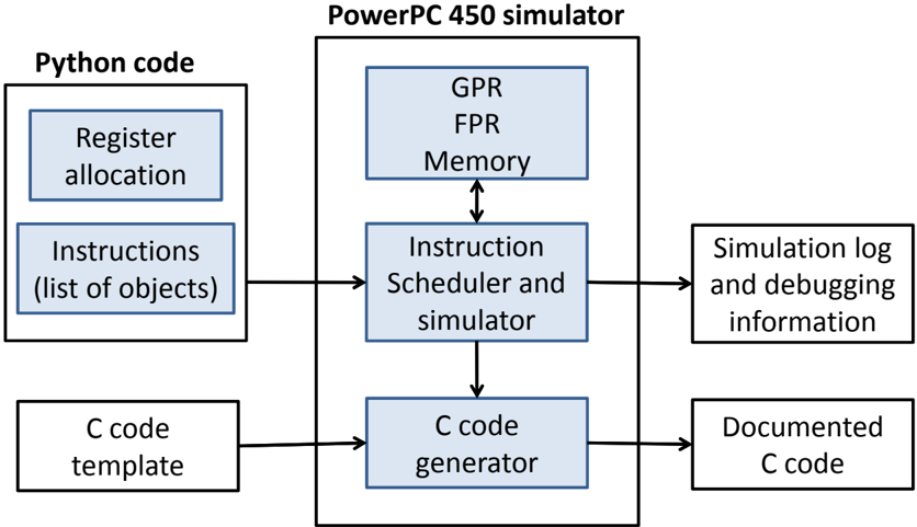
The image is a system architecture block diagram illustrating the workflow of a "PowerPC 450 simulator." The diagram depicts a process where Python-based instructions and C-code templates are processed by a central simulator engine to produce debugging logs and documented C code. The system is organized into three primary functional regions: input (left), processing (center), and output (right).
### Components/Axes
The diagram uses rectangular boxes to represent functional modules. Some boxes are shaded in light blue, while others are white. Arrows indicate the direction of data flow and control.
**Regions:**
* **Left Region:** Contains the "Python code" container.
* **Center Region:** Contains the "PowerPC 450 simulator" container.
* **Bottom-Left:** Contains the "C code template" block.
* **Right Region:** Contains the output blocks.
### Detailed Analysis
#### 1. Python Code (Top-Left)
This region is enclosed in a white box labeled "Python code." It contains two light-blue stacked boxes:
* **Top:** "Register allocation"
* **Bottom:** "Instructions (list of objects)"
* **Flow:** An arrow points from the "Instructions (list of objects)" block to the right, entering the "Instruction Scheduler and simulator" block in the center region.
#### 2. PowerPC 450 Simulator (Center)
This is the core processing unit, enclosed in a large black-bordered box labeled "PowerPC 450 simulator." It contains three light-blue boxes:
* **Top:** "GPR, FPR, Memory" (GPR = General Purpose Registers; FPR = Floating Point Registers).
* **Middle:** "Instruction Scheduler and simulator."
* **Bottom:** "C code generator."
**Internal Flows:**
* There is a **bidirectional arrow** connecting "GPR, FPR, Memory" and "Instruction Scheduler and simulator," indicating constant state read/write access.
* There is a **vertical arrow** pointing downward from "Instruction Scheduler and simulator" to "C code generator."
#### 3. C Code Template (Bottom-Left)
A white box labeled "C code template" sits outside the main simulator box. An arrow points from this block to the right, entering the "C code generator" block inside the simulator.
#### 4. Outputs (Right)
Two white boxes are positioned to the right of the simulator:
* **Top:** "Simulation log and debugging information." An arrow points from the "Instruction Scheduler and simulator" to this block.
* **Bottom:** "Documented C code." An arrow points from the "C code generator" to this block.
### Key Observations
* **Centrality:** The "Instruction Scheduler and simulator" acts as the central hub of the architecture, managing both the state (GPR/FPR/Memory) and the flow of data to the outputs.
* **Dual-Path Processing:** The system processes inputs through two distinct paths:
1. **Simulation Path:** Python instructions are executed by the scheduler, resulting in logs and debugging data.
2. **Generation Path:** The scheduler interacts with the "C code generator," which combines the logic with a "C code template" to produce "Documented C code."
* **State Management:** The bidirectional link between the scheduler and the register/memory block confirms that the simulator is stateful, tracking the processor's internal state during execution.
### Interpretation
This diagram represents a **simulation-to-code generation pipeline**. It demonstrates a workflow where a user defines a program using high-level Python objects (likely defining register allocation and instruction sequences).
The "PowerPC 450 simulator" serves two purposes:
1. **Validation:** By running the instructions against the simulated registers and memory, it generates logs for debugging, allowing the user to verify the logic of their Python-defined program.
2. **Transpilation/Deployment:** By passing the instruction flow to the "C code generator" alongside a "C code template," the system converts the high-level Python definition into a deployable, documented C-code implementation.
This architecture is typical of hardware/software co-design tools where a high-level language (Python) is used to model or verify hardware behavior before generating the final low-level implementation (C code).