## Diagram: PowerPC 450 Simulator System Architecture
### Overview
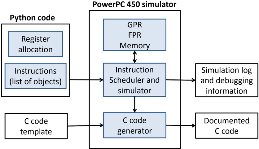
The image is a technical block diagram illustrating the architecture and data flow of a system for simulating and generating code for a PowerPC 450 processor. The diagram shows the interaction between Python-based front-end components, a central simulator, and output artifacts. The primary language is English.
### Components
The diagram is composed of several labeled rectangular blocks connected by directional arrows indicating data or control flow.
**Left Side (Inputs):**
1. **Python code** (Top-left container box)
* Contains two sub-blocks:
* `Register allocation`
* `Instructions (list of objects)`
2. **C code template** (Bottom-left box)
**Center (Core System):**
3. **PowerPC 450 simulator** (Large central container box)
* Contains three internal blocks:
* `GPR / FPR / Memory` (Top block)
* `Instruction Scheduler and simulator` (Middle block)
* `C code generator` (Bottom block)
**Right Side (Outputs):**
4. **Simulation log and debugging information** (Top-right box)
5. **Documented C code** (Bottom-right box)
### Detailed Analysis
The diagram defines a clear pipeline with the following data flows:
1. **From Python Code to Simulator:** The `Instructions (list of objects)` block has a single-headed arrow pointing to the `Instruction Scheduler and simulator` block within the simulator. This indicates the instruction list is the primary input for simulation.
2. **Internal Simulator Flow:**
* The `Instruction Scheduler and simulator` has a **bidirectional arrow** connecting it to the `GPR / FPR / Memory` block. This signifies that the scheduler reads from and writes to the processor's General Purpose Registers (GPR), Floating-Point Registers (FPR), and Memory during simulation.
* A single-headed arrow points downward from the `Instruction Scheduler and simulator` to the `C code generator`.
3. **From C Code Template to Generator:** The `C code template` box has a single-headed arrow pointing to the `C code generator` block.
4. **Outputs from the Simulator:**
* The `Instruction Scheduler and simulator` has a single-headed arrow pointing to the `Simulation log and debugging information` output.
* The `C code generator` has a single-headed arrow pointing to the `Documented C code` output.
### Key Observations
* **Separation of Concerns:** The architecture cleanly separates the high-level description (Python code) from the simulation engine and the code generation backend.
* **Central Role of the Scheduler:** The `Instruction Scheduler and simulator` is the central hub, interacting with all other major components: receiving instructions, managing state (GPR/FPR/Memory), producing logs, and feeding the code generator.
* **Dual Output Pathways:** The system produces two distinct outputs: runtime/debug information (`Simulation log...`) and a static artifact (`Documented C code`).
* **Template-Driven Generation:** The `C code generator` does not work from scratch; it uses a `C code template` as a foundation, suggesting a framework or boilerplate approach to code generation.
### Interpretation
This diagram represents a **model-based development or simulation toolchain** for the PowerPC 450 architecture. The system's purpose is to take a high-level, object-oriented description of instructions (written in Python), simulate their execution on a detailed model of the processor (including registers and memory), and simultaneously generate corresponding, well-documented C code.
The **key relationship** is between simulation and generation. The same instruction list drives both processes, ensuring functional consistency between the simulated behavior and the generated code. The `C code template` implies the generated code is meant to be integrated into a larger project or used as a reference implementation.
The **notable anomaly** is the lack of a direct connection from the `Register allocation` block to any other component. It is contained within the `Python code` box but has no outgoing arrows. This suggests it may be a preparatory step that operates on the instruction list *before* it is passed to the simulator, or its output is implicitly part of the `Instructions (list of objects)`. Its isolation is a point of ambiguity in the diagram.
In essence, this is a **code synthesis and verification pipeline**. It allows developers to write and verify algorithms at a higher level of abstraction (Python objects) while automatically producing optimized, documented, and verifiable C code for the target hardware, with simulation logs providing a trace for debugging and validation.