## Diagram: Robot Sensor Configuration and Physical Prototype
### Overview
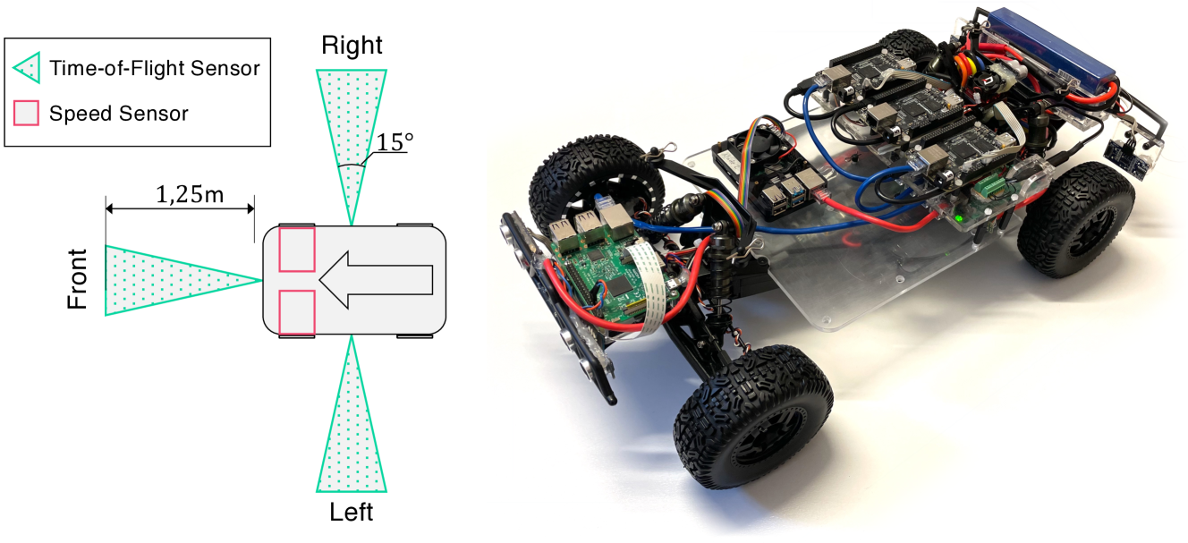
The image contains two sections:
1. **Left**: A technical diagram illustrating sensor placement and orientation on a robot chassis.
2. **Right**: A photograph of the physical robot prototype, showcasing its internal components and wiring.
---
### Components/Axes
#### Left Diagram (Sensor Configuration)
- **Legend**:
- **Time-of-Flight (ToF) Sensor**: Green triangle (▲)
- **Speed Sensor**: Red square (■)
- **Labels**:
- **Front**: Central axis with a 1.25m measurement line.
- **Right/Left**: Angled ToF sensors at ±15° from the front axis.
- **Key Elements**:
- Two red squares (Speed Sensors) aligned along the robot’s longitudinal axis.
- Three green triangles (ToF Sensors): one at the front, one at 15° to the right, and one at 15° to the left.
#### Right Photograph (Robot Prototype)
- **Structure**:
- Four-wheeled chassis with large off-road tires.
- Transparent plastic body revealing internal electronics.
- **Components**:
- **Power System**: Blue battery pack mounted at the rear.
- **Control Board**: Green circuit board with microcontrollers and sensors.
- **Wiring**: Red, blue, and yellow cables connecting motors, sensors, and power.
- **Mounting**: Metal brackets securing wheels and electronic modules.
---
### Detailed Analysis
#### Left Diagram
- **Sensor Placement**:
- **ToF Sensors**:
- Front: Directly aligned with the 1.25m measurement line.
- Right/Left: Positioned at 15° angles from the front axis, suggesting a 30° total field of view for obstacle detection.
- **Speed Sensors**:
- Located symmetrically along the robot’s centerline, likely for differential drive control.
- **Uncertainties**:
- The 15° angle is explicitly labeled only on the right side; symmetry is assumed for the left.
- The 1.25m distance is a linear measurement but lacks context for sensor range (e.g., detection resolution).
#### Right Photograph
- **Component Relationships**:
- The green circuit board (control hub) is centrally located, with motors and wheels at the extremities.
- Wiring follows a star topology, connecting all components to the central board.
- **Notable Details**:
- Exposed wiring and modular design suggest ease of maintenance or customization.
- The blue battery pack is positioned at the rear, balancing weight distribution.
---
### Key Observations
1. **Sensor Coverage**:
- ToF sensors provide a 30° field of view (15° left/right), enabling obstacle detection in a wide arc.
- Speed sensors are critical for real-time motor feedback, essential for precise movement.
2. **Design Trade-offs**:
- The transparent chassis prioritizes accessibility over aerodynamics, indicating a focus on prototyping or educational use.
- Exposed wiring may increase vulnerability to environmental factors (e.g., dust, moisture).
---
### Interpretation
- **Functionality**:
The robot integrates **ToF sensors** for spatial awareness and **Speed Sensors** for motor control, suggesting applications in autonomous navigation or robotic competitions.
- **Design Intent**:
The modular, open architecture implies a focus on experimentation, allowing users to modify sensor configurations or add components.
- **Limitations**:
The 1.25m ToF range may restrict performance in cluttered environments, and the lack of enclosure for wiring could reduce durability.
This configuration balances simplicity and functionality, making it suitable for educational robotics or hobbyist projects.