## Logical Reasoning with Visual Scenes
### Overview
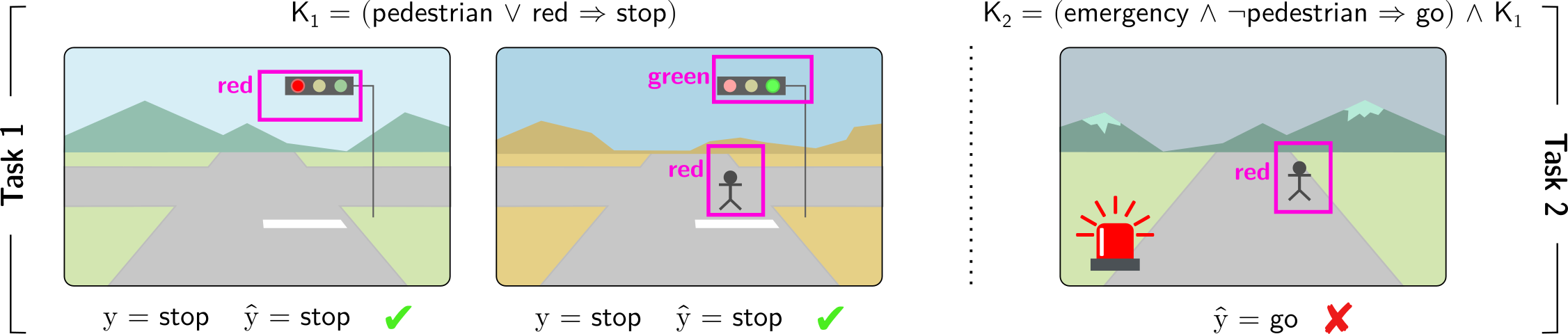
The image presents a series of visual scenes depicting traffic scenarios, each associated with a logical rule and a predicted outcome. The scenes are divided into two tasks, each involving a different set of conditions and rules. The image evaluates the correctness of the predicted outcomes based on the given rules and visual inputs.
### Components/Axes
* **Task 1**: Labeled vertically on the left side of the first two images.
* **Task 2**: Labeled vertically on the right side of the third image.
* **Visual Scenes**: Three distinct scenes depicting roads, traffic lights, pedestrians, and emergency vehicles.
* **Logical Rules**:
* K1 = (pedestrian ∨ red → stop)
* K2 = (emergency ∧ ¬pedestrian → go) ∧ K1
* **Object Detection**: Magenta bounding boxes around traffic lights and pedestrians, with labels indicating the color of the traffic light (red or green) or the presence of a pedestrian (red).
* **Predicted Outcomes**: "y = stop", "ŷ = stop", "ŷ = go"
* **Correctness Indicators**: Green checkmark for correct predictions, red "X" for incorrect predictions.
### Detailed Analysis
**Scene 1 (Task 1)**
* **Visual Elements**: A road scene with a traffic light showing red. The background includes mountains and a sky.
* **Object Detection**: A magenta box surrounds the traffic light, labeled "red".
* **Logical Rule**: K1 = (pedestrian ∨ red → stop)
* **Predicted Outcome**: y = stop, ŷ = stop
* **Correctness**: Green checkmark, indicating the prediction is correct.
**Scene 2 (Task 1)**
* **Visual Elements**: A road scene with a traffic light showing green and a pedestrian crossing. The background includes mountains and a sky.
* **Object Detection**: A magenta box surrounds the traffic light, labeled "green". Another magenta box surrounds the pedestrian, labeled "red".
* **Logical Rule**: K1 = (pedestrian ∨ red → stop)
* **Predicted Outcome**: y = stop, ŷ = stop
* **Correctness**: Green checkmark, indicating the prediction is correct.
**Scene 3 (Task 2)**
* **Visual Elements**: A road scene with a pedestrian crossing and an emergency vehicle with flashing red lights. The background includes mountains and a sky.
* **Object Detection**: A magenta box surrounds the pedestrian, labeled "red". The emergency vehicle is also visible.
* **Logical Rule**: K2 = (emergency ∧ ¬pedestrian → go) ∧ K1
* **Predicted Outcome**: ŷ = go
* **Correctness**: Red "X", indicating the prediction is incorrect.
### Key Observations
* Task 1 focuses on the basic rule of stopping at a red light or when a pedestrian is present.
* Task 2 introduces an additional rule involving emergency vehicles and the absence of pedestrians.
* The third scene highlights a potential conflict between the two rules, where the presence of an emergency vehicle might suggest "go," but the presence of a pedestrian should override this and require a "stop."
### Interpretation
The image demonstrates a system for evaluating logical reasoning in visual scenes. The system uses object detection to identify relevant elements (traffic lights, pedestrians, emergency vehicles), applies logical rules to these elements, and predicts an outcome (stop or go). The correctness of the prediction is then assessed.
The incorrect prediction in the third scene suggests a limitation in the system's ability to resolve conflicts between different rules or to prioritize rules based on context. Specifically, the system incorrectly predicts "go" when an emergency vehicle is present, even though a pedestrian is also present, which should trigger the "stop" rule. This highlights the need for more sophisticated reasoning mechanisms that can handle complex scenarios and prioritize rules appropriately.