\n
## Diagram: Autonomous Vehicle Task Scenarios
### Overview
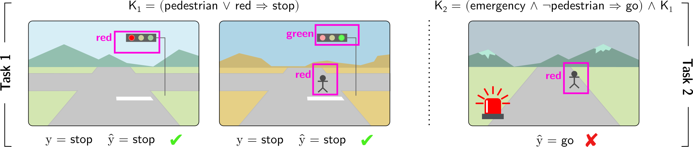
The image presents a diagram illustrating two distinct tasks (Task 1 and Task 2) for an autonomous vehicle, focusing on pedestrian and traffic light interactions. Each task is visually represented with a scene depicting a road, pedestrian(s), and traffic lights. Logical conditions (K1 and K2) are provided above each task, defining the expected behavior. Below each scene, the actual output (y) and predicted output (ŷ) are shown, along with a correctness indicator (check or cross).
### Components/Axes
The diagram is divided into two main sections labeled "Task 1" and "Task 2" on the left and right sides, respectively. Each task section contains:
* **Scene:** A visual representation of a road with surrounding environment (mountains, sidewalks).
* **Traffic Light:** Displayed in different states (red, green).
* **Pedestrian:** Represented by a purple stick figure.
* **Logical Condition:** A mathematical expression (K1, K2) defining the expected behavior.
* **Output:** "y" represents the actual output, and "ŷ" represents the predicted output.
* **Correctness Indicator:** A checkmark (✓) indicates a correct prediction, while a cross (✗) indicates an incorrect prediction.
### Detailed Analysis or Content Details
**Task 1:**
* **Scene 1:** Traffic light is red. Pedestrian is not present.
* K1 = (pedestrian ∨ red → stop)
* y = stop
* ŷ = stop (✓)
* **Scene 2:** Traffic light is green. Pedestrian is not present.
* K1 = (pedestrian ∨ red → stop)
* y = stop
* ŷ = stop (✓)
* **Scene 3:** Traffic light is red. Pedestrian is present.
* K1 = (pedestrian ∨ red → stop)
* y = stop
* ŷ = stop (✓)
**Task 2:**
* **Scene 1:** Traffic light is red. Pedestrian is present.
* K2 = (emergency ∧ ¬pedestrian → go) ∧ K1
* ŷ = go (✗)
**Logical Conditions Breakdown:**
* **K1:** "pedestrian ∨ red → stop" - If a pedestrian is present OR the traffic light is red, then the vehicle should stop.
* **K2:** "(emergency ∧ ¬pedestrian → go) ∧ K1" - If there is an emergency AND no pedestrian is present, then the vehicle should go, AND K1 must also be true. The "¬" symbol represents negation (NOT).
### Key Observations
* Task 1 consistently shows correct predictions (all checkmarks). The autonomous vehicle correctly interprets the traffic light and pedestrian presence to determine whether to stop.
* Task 2 has an incorrect prediction. The vehicle incorrectly predicted "go" when a pedestrian was present and the traffic light was red. This suggests a failure to correctly apply the K2 condition, specifically the interaction with K1.
### Interpretation
The diagram demonstrates the logical reasoning expected of an autonomous vehicle in navigating pedestrian and traffic light scenarios. The use of logical conditions (K1 and K2) formalizes the decision-making process. The incorrect prediction in Task 2 highlights a potential flaw in the vehicle's logic, specifically in prioritizing emergency situations over pedestrian safety when K1 is also active. The diagram serves as a test case to validate the autonomous vehicle's decision-making capabilities and identify areas for improvement in its programming. The use of logical notation (∨, ∧, →, ¬) suggests a formal verification or testing framework is being employed. The diagram is not presenting numerical data, but rather a logical evaluation of the system's behavior.