## System Diagram: Multiprocessor System Architecture
### Overview
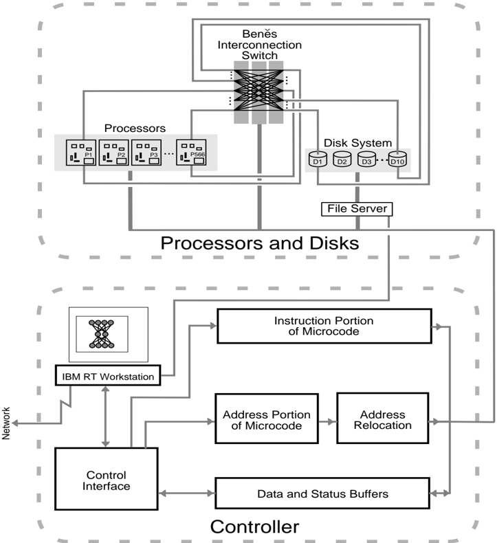
The image is a system diagram illustrating the architecture of a multiprocessor system. It shows the interconnection of processors, a disk system, and a controller, highlighting data flow and control mechanisms.
### Components/Axes
* **Processors:** A group of processors labeled P1, P2, P3, and P566.
* **Beněs Interconnection Switch:** A switch that connects the processors to the disk system.
* **Disk System:** A set of disks labeled D1, D2, D3, and D10.
* **File Server:** A component connecting the processors and disks.
* **IBM RT Workstation:** A workstation connected to the controller.
* **Control Interface:** An interface for controlling the system.
* **Instruction Portion of Microcode:** A component related to microcode instructions.
* **Address Portion of Microcode:** A component related to microcode addresses.
* **Address Relocation:** A component for address relocation.
* **Data and Status Buffers:** Buffers for data and status information.
* **Network:** A connection to a network.
* **Processors and Disks:** A grouping of the processors, interconnection switch, disk system, and file server.
* **Controller:** A grouping of the IBM RT Workstation, Control Interface, Instruction Portion of Microcode, Address Portion of Microcode, Address Relocation, and Data and Status Buffers.
### Detailed Analysis
* **Processors:** Four processors are explicitly labeled: P1, P2, P3, and P566. The processors are connected to the Beněs Interconnection Switch.
* **Beněs Interconnection Switch:** This switch facilitates communication between the processors and the disk system. It is positioned at the top-center of the diagram.
* **Disk System:** The disk system consists of four disks: D1, D2, D3, and D10. It is connected to the Beněs Interconnection Switch.
* **File Server:** The file server acts as an intermediary between the processors and the disk system.
* **IBM RT Workstation:** The workstation is connected to the Control Interface and the Instruction Portion of Microcode.
* **Control Interface:** The control interface is connected to the IBM RT Workstation, the Data and Status Buffers, and the Address Portion of Microcode.
* **Instruction Portion of Microcode:** This component is connected to the IBM RT Workstation and the Data and Status Buffers.
* **Address Portion of Microcode:** This component is connected to the Control Interface and the Address Relocation component.
* **Address Relocation:** This component is connected to the Address Portion of Microcode and the Data and Status Buffers.
* **Data and Status Buffers:** This component is connected to the Control Interface, the Instruction Portion of Microcode, and the Address Relocation component.
* **Network:** The network is connected to the IBM RT Workstation.
### Key Observations
* The diagram shows a clear separation between the "Processors and Disks" section and the "Controller" section.
* The Beněs Interconnection Switch is a key component for connecting processors and disks.
* The IBM RT Workstation appears to be a central point for control and monitoring.
* The flow of data and control signals is indicated by arrows.
### Interpretation
The diagram illustrates a multiprocessor system architecture where multiple processors can access a shared disk system through an interconnection switch. The controller manages the operation of the system, with the IBM RT Workstation providing a user interface. The microcode components (Instruction Portion, Address Portion, and Address Relocation) likely handle low-level control and memory management. The data and status buffers facilitate communication between different components of the controller. The network connection allows for remote access and monitoring of the system. The architecture suggests a system designed for parallel processing and data-intensive applications.