\n
## Diagram: System Architecture
### Overview
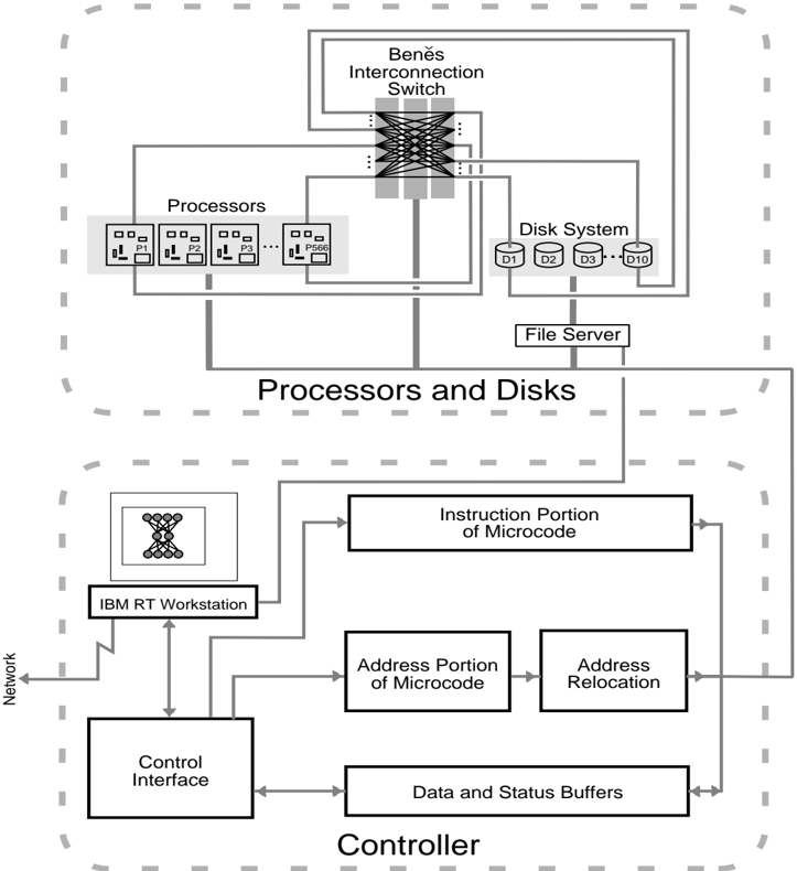
The image depicts a high-level system architecture diagram, likely representing a distributed computing or parallel processing system. It shows the interconnection between processors, disk systems, a file server, and a controller, along with an IBM RT Workstation. The diagram is enclosed within a dashed border, suggesting a modular or bounded system.
### Components/Axes
The diagram is composed of several key components:
* **Benes Interconnection Switch:** Located at the top-center.
* **Processors:** A block labeled "Processors" containing six processor units labeled P1 through P6.
* **Disk System:** A block labeled "Disk System" containing ten disk units labeled D1 through D10.
* **File Server:** Located between the Processors and Disk System.
* **IBM RT Workstation:** Located in the lower-left section.
* **Controller:** A block labeled "Controller" containing several sub-components: Control Interface, Data and Status Buffers, Address Portion of Microcode, Instruction Portion of Microcode, and Address Relocation.
* **Network:** A connection labeled "Network" leading to the IBM RT Workstation.
* **Arrows:** Representing data flow and connections between components.
There are no explicit axes or scales in this diagram. It is a schematic representation of system components and their interconnections.
### Detailed Analysis or Content Details
The diagram illustrates the following connections and relationships:
* The Benes Interconnection Switch connects the Processors and the Disk System. The switch appears to have multiple input/output lines, suggesting a complex routing capability.
* The File Server is connected to both the Processors and the Disk System, acting as an intermediary for data access.
* The IBM RT Workstation is connected to the Controller via the Network.
* The Controller's Control Interface is connected to the IBM RT Workstation.
* The Controller's Data and Status Buffers are connected to the Address Relocation and Address Portion of Microcode.
* The Instruction Portion of Microcode is connected to the Address Portion of Microcode.
* The Controller is connected to the Network.
The diagram does not provide specific numerical data or performance metrics. It focuses on the architectural arrangement of the system.
### Key Observations
* The Benes Interconnection Switch is a central component, suggesting its importance in managing communication between processors and disks.
* The Controller acts as a bridge between the IBM RT Workstation and the core processing/storage components.
* The separation of Instruction and Address portions of microcode within the Controller suggests a sophisticated control mechanism.
* The diagram highlights a layered architecture, with the IBM RT Workstation at the top level, the Controller as an intermediary, and the Processors and Disks at the lower level.
### Interpretation
This diagram likely represents a parallel processing system designed for high-performance computing. The Benes Interconnection Switch enables efficient communication between processors and disks, allowing for parallel data access and processing. The File Server provides a centralized storage and access point for data. The IBM RT Workstation serves as a user interface and control point for the system. The Controller manages the flow of instructions and data between the workstation and the core processing components.
The architecture suggests a focus on scalability and flexibility. The modular design allows for the addition of more processors and disks as needed. The Benes Interconnection Switch provides a dynamic routing capability, enabling efficient communication even as the system grows. The separation of instruction and address portions of microcode within the Controller suggests a sophisticated control mechanism that can optimize performance and manage complex tasks.
The diagram does not reveal specific details about the system's performance characteristics or limitations. However, it provides a clear overview of its architectural design and key components. The use of a Benes network suggests a focus on minimizing communication bottlenecks and maximizing parallel processing efficiency. The inclusion of an IBM RT Workstation indicates that the system was likely developed in the 1980s or early 1990s, a period when IBM RT workstations were commonly used for high-performance computing applications.