## Diagram: High-Level System Architecture
### Overview
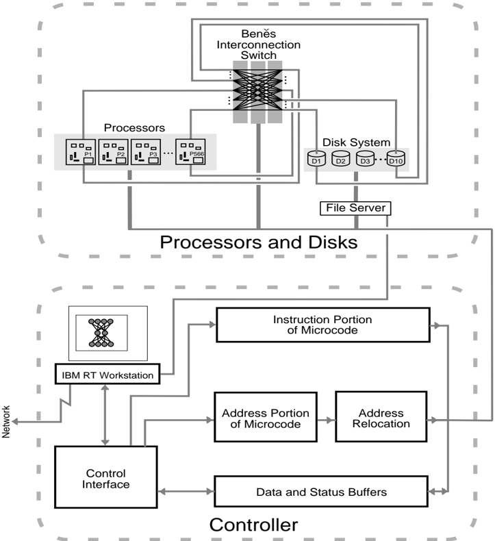
The diagram illustrates a distributed computing system architecture divided into two primary sections: **Processors and Disks** (top) and **Controller** (bottom). Components are interconnected via labeled pathways, with directional arrows indicating data flow.
### Components/Axes
#### Processors and Disks Section
- **Processors**: Labeled P1, P2, P3, ..., P566 (grid layout).
- **Benes Interconnection Switch**: Central hub connecting processors to disk systems and file servers.
- **Disk System**: Disks labeled D1, D2, D3, ..., D10 (linear arrangement).
- **File Server**: Connected to the disk system.
#### Controller Section
- **IBM RT Workstation**: Connected to the **Control Interface**.
- **Control Interface**: Links to **Data and Status Buffers**, **Address Portion of Microcode**, **Address Relocation**, and **Instruction Portion of Microcode**.
- **Network**: External connection to the IBM RT Workstation.
### Detailed Analysis
- **Processors and Disks**:
- Processors (P1–P566) are arranged in a grid, suggesting parallel processing capabilities.
- The Benes Interconnection Switch enables high-speed, non-blocking communication between processors and storage.
- Disk System (D1–D10) and File Server are connected via dedicated pathways, indicating centralized storage management.
- **Controller**:
- The IBM RT Workstation acts as a control node, feeding data into the **Control Interface**.
- **Data and Status Buffers** likely serve as temporary storage for intermediate results.
- **Address Portion of Microcode** and **Instruction Portion of Microcode** suggest modular firmware/software control logic.
- **Address Relocation** implies dynamic memory management or virtual addressing.
### Key Observations
1. **Hierarchical Design**: The system separates computational resources (processors/disks) from control logic (controller), enabling modular scalability.
2. **Benes Switch Role**: Centralized interconnect ensures efficient data routing between processors and storage, critical for parallel workloads.
3. **Controller Complexity**: The controller integrates firmware (microcode) and hardware interfaces, indicating tight integration between software and hardware layers.
### Interpretation
This architecture prioritizes **parallelism** (via the Benes switch and processor grid) and **centralized control** (via the IBM RT Workstation and Control Interface). The Benes switch’s non-blocking topology minimizes latency in data transfers, while the controller’s modular design allows flexible firmware updates. The IBM RT Workstation’s role as a control node suggests it manages orchestration of tasks across processors and storage.
Notably, the absence of explicit latency or throughput metrics implies the diagram focuses on structural relationships rather than performance benchmarks. The system likely targets high-throughput, low-latency applications such as scientific computing or database management.