# Technical Document: System Design - Architecture
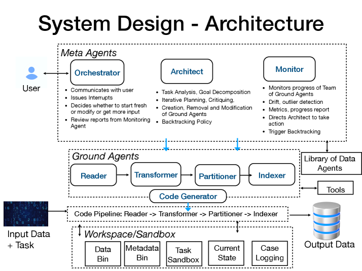
This document provides a comprehensive extraction and analysis of the "System Design - Architecture" diagram. The architecture describes a multi-agent system composed of high-level "Meta Agents" that manage a pipeline of "Ground Agents" to process data and tasks within a sandboxed environment.
---
## 1. Document Header
* **Title:** System Design - Architecture
---
## 2. Component Isolation and Analysis
The diagram is organized into four primary horizontal layers and several peripheral components.
### A. User Interface (Left)
* **Entity:** User (represented by a blue person icon).
* **Interaction:** Bi-directional arrow connecting the User to the **Orchestrator** within the Meta Agents block.
### B. Meta Agents (Top Layer)
Contained within a dashed rectangular boundary. These agents provide high-level governance and planning.
#### **1. Orchestrator**
* **Role:** Primary interface and decision-maker.
* **Responsibilities:**
* Communicates with user.
* Issues Interrupts.
* Decides whether to start fresh or modify or get more input.
* Review reports from Monitoring Agent.
#### **2. Architect**
* **Role:** Strategic planner and agent manager.
* **Responsibilities:**
* Task Analysis, Goal Decomposition.
* Iterative Planning, Critiquing.
* Creation, Removal and Modification of Ground Agents.
* Backtracking Policy.
#### **3. Monitor**
* **Role:** Quality assurance and oversight.
* **Responsibilities:**
* Monitors progress of Team of Ground Agents.
* Drift, outlier detection.
* Metrics, progress report.
* Directs Architect to take action.
* Trigger Backtracking.
---
### C. Ground Agents (Middle Layer)
Contained within a dashed rectangular boundary. These are the functional units that execute the data processing.
* **Workflow Sequence:** Reader $\rightarrow$ Transformer $\rightarrow$ Partitioner $\rightarrow$ Indexer.
* **Code Generator:** Positioned below the sequence, receiving input from the Ground Agents block to produce the execution pipeline.
---
### D. Execution & Storage (Bottom Layer)
This section details the actual data flow and the environment where work is performed.
#### **Input Data + Task**
* Represented by a dark digital/binary image on the left.
* Feeds directly into the **Code Pipeline**.
#### **Code Pipeline**
* **Definition:** Reader $\rightarrow$ Transformer $\rightarrow$ Partitioner $\rightarrow$ Indexer.
* This pipeline is generated by the **Code Generator** (indicated by a downward blue arrow).
#### **Workspace/Sandbox**
A dashed rectangular boundary containing five sub-components for state management:
1. **Data Bin**
2. **Metadata Bin**
3. **Task Sandbox**
4. **Current State**
5. **Case Logging**
* **Interaction:** Bi-directional arrows connect the Workspace/Sandbox to the Code Pipeline.
#### **Output Data**
* Represented by a 3D cylinder/database icon on the right.
* Receives the final results from the **Code Pipeline**.
---
### E. External Resources (Right Side)
* **Library of Data Agents:** Connected via bi-directional arrow to the Meta Agents block.
* **Tools:** Connected via bi-directional arrow to the Ground Agents block.
---
## 3. System Flow and Logic
1. **Initiation:** The **User** provides a task to the **Orchestrator**.
2. **Planning:** The **Architect** decomposes the task and determines which **Ground Agents** are needed, drawing from the **Library of Data Agents**.
3. **Generation:** The **Code Generator** creates a specific **Code Pipeline** based on the Ground Agents' logic.
4. **Execution:** The **Input Data + Task** is processed through the pipeline. During this process, the pipeline interacts with the **Workspace/Sandbox** to store intermediate states, logs, and metadata.
5. **Monitoring:** The **Monitor** observes the Ground Agents' progress. If drift or errors are detected, it triggers the **Architect** to modify the plan or initiates **Backtracking**.
6. **Completion:** The processed information is committed to **Output Data**.