## System Architecture Diagram: Memory and Processing Unit Interaction
### Overview
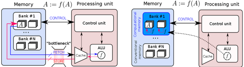
The image presents two diagrams illustrating the interaction between memory and a processing unit. The left diagram depicts a conventional memory architecture, while the right diagram shows a computational memory architecture. Both diagrams highlight the flow of data and control signals between the memory banks and the processing unit components.
### Components/Axes
**Left Diagram (Conventional Memory):**
* **Memory:** Labeled "Memory" at the top. Contains two memory banks: "Bank #1" and "Bank #N". Each bank contains multiple memory locations represented by small rectangles.
* The memory banks are enclosed in a light blue rounded rectangle.
* **Processing Unit:** Labeled "Processing unit" at the top. Contains a "Control unit", "ALU" (Arithmetic Logic Unit), and "Cache".
* The processing unit is enclosed in a light red rounded rectangle.
* **Data Flow:**
* **FETCH:** Data is fetched from memory to the cache via a "bottleneck". The "FETCH" label is associated with a red arrow pointing from the memory to the cache.
* **STORE:** Data is stored from the cache to memory. The "STORE" label is associated with a pink arrow pointing from the cache to the memory.
* **Control:** Control signals are sent from the control unit to the memory. The "CONTROL" label is associated with a blue arrow pointing from the control unit to Bank #1.
* Data flows between Bank #1 and Bank #N via pink and blue arrows.
* **Equation:** "A := f(A)" is displayed above the processing unit, indicating that the processing unit applies a function 'f' to data 'A'.
**Right Diagram (Computational Memory):**
* **Memory:** Labeled "Memory" at the top. Contains two memory banks: "Bank #1" and "Bank #N". Each bank contains multiple memory locations represented by small rectangles.
* Bank #1 is labeled as "Computational memory" and is enclosed in a blue rounded rectangle.
* Bank #N is labeled as "Conventional memory" and is enclosed in a white rounded rectangle.
* **Processing Unit:** Labeled "Processing unit" at the top. Contains a "Control unit", "ALU" (Arithmetic Logic Unit), and "Cache".
* The processing unit is enclosed in a light red rounded rectangle.
* **Data Flow:**
* The function 'f' is applied directly within the computational memory bank (Bank #1), indicated by small pink arrows and 'f' labels within the bank.
* **Control:** Control signals are sent from the control unit to the memory. The "CONTROL" label is associated with a blue arrow pointing from the control unit to Bank #1.
* A dashed black arrow indicates a potential data flow path from the computational memory to the cache.
* **Equation:** "A := f(A)" is displayed above the processing unit, indicating that the processing unit applies a function 'f' to data 'A'.
### Detailed Analysis or ### Content Details
**Left Diagram (Conventional Memory):**
* Data 'A' is stored in Bank #1.
* The "bottleneck" suggests a limitation in the data transfer rate between memory and cache.
* The ALU performs the function 'f' on data fetched from memory.
* The control unit manages the data flow and operations.
**Right Diagram (Computational Memory):**
* Data 'A' is stored in Bank #1 (Computational Memory).
* The function 'f' is applied directly within the memory bank, reducing the need to transfer data to the ALU for processing.
* The dashed arrow suggests that the processed data can be sent to the cache if needed.
* Bank #N (Conventional Memory) operates similarly to the memory banks in the left diagram.
### Key Observations
* The primary difference between the two diagrams is the location where the function 'f' is applied. In the conventional memory architecture, 'f' is applied in the ALU within the processing unit. In the computational memory architecture, 'f' is applied directly within the memory bank.
* The "bottleneck" label in the conventional memory diagram highlights a potential performance limitation.
* The computational memory architecture aims to improve performance by reducing data transfer between memory and the processing unit.
### Interpretation
The diagrams illustrate the evolution from a conventional memory architecture to a computational memory architecture. The conventional architecture requires data to be transferred to the processing unit for computation, which can be a bottleneck. The computational memory architecture aims to overcome this bottleneck by performing computations directly within the memory bank. This reduces data transfer, potentially leading to improved performance and energy efficiency. The dashed arrow in the computational memory diagram suggests that the processed data can still be accessed by the processing unit if needed, providing flexibility in the system design.