\n
## System Architecture Diagram: Neuro-Symbolic Training Pipeline
### Overview
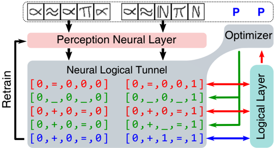
The image is a technical diagram illustrating a neuro-symbolic machine learning architecture. It depicts a closed-loop training process where a neural perception component interacts with a logical reasoning component, mediated by an optimizer. The system appears designed to integrate pattern recognition (neural) with symbolic logic.
### Components/Axes
The diagram is organized into several interconnected blocks and data flows:
1. **Input Layer (Top):** Two dashed boxes containing sequences of symbols.
* **Left Box:** Contains the sequence: `∞ ≈ ∞ π ∞`
* **Right Box:** Contains the sequence: `∞ ≈ IN π N`
* To the right of these boxes are two standalone blue letters: `P P`.
2. **Perception Neural Layer (Upper Middle):** A pink rectangular block labeled "Perception Neural Layer". It receives input from the symbol sequences above via two downward arrows.
3. **Neural Logical Tunnel (Center):** A large grey block labeled "Neural Logical Tunnel". It contains two vertical columns of 5 arrays each. Each array has 5 elements, which are numbers (0, 1) or symbols (=, +, _).
* **Left Column Arrays:**
1. `[0, =, 0, 0, 0]` (Text color: Red)
2. `[0, _, 0, _, 0]` (Text color: Green)
3. `[0, +, 0, =, 0]` (Text color: Red)
4. `[0, +, 0, =, 0]` (Text color: Green)
5. `[0, +, 0, =, 0]` (Text color: Blue)
* **Right Column Arrays:**
1. `[0, =, 0, 0, 1]` (Text color: Red)
2. `[0, _, 0, 0, 1]` (Text color: Green)
3. `[0, +, 0, =, 1]` (Text color: Red)
4. `[0, +, _, =, 1]` (Text color: Green)
5. `[0, +, 1, =, 1]` (Text color: Blue)
4. **Logical Layer (Right):** A light blue vertical block labeled "Logical Layer". It is connected to the Neural Logical Tunnel via a set of colored arrows.
5. **Optimizer (Upper Right):** A grey block labeled "Optimizer". It receives input from the Logical Layer (red upward arrow) and sends output to the Perception Neural Layer (black arrow pointing left).
6. **Retrain Loop (Left):** A black arrow labeled "Retrain" originates from the Optimizer and points back to the input of the Perception Neural Layer, completing a feedback cycle.
7. **Legend/Connection Key (Right of Tunnel):** Three colored arrows define the connection scheme between the Neural Logical Tunnel and the Logical Layer:
* **Red Arrow:** Connects to the **1st and 3rd** arrays in both the left and right columns.
* **Green Arrow:** Connects to the **2nd and 4th** arrays in both the left and right columns.
* **Blue Arrow:** Connects to the **5th** array in both the left and right columns.
### Detailed Analysis
* **Data Flow:** The process flows from top to bottom and then loops back.
1. Symbolic inputs are fed into the Perception Neural Layer.
2. The Perception Layer outputs to the Neural Logical Tunnel, which generates two sets of logical statements or feature vectors (the arrays).
3. These arrays are routed, based on their color-coded category (Red, Green, Blue), to the Logical Layer.
4. The Logical Layer processes this information and sends a signal to the Optimizer.
5. The Optimizer computes an update and sends it back via the "Retrain" path to update the Perception Neural Layer, closing the loop.
* **Array Content Pattern:** The arrays in the right column are nearly identical to their left-column counterparts, with a key difference: the **last element** in every right-column array is `1`, whereas in the left column it is `0`. This suggests the right column may represent a "true" or "activated" state of the logical propositions defined by the first four elements.
### Key Observations
1. **Color-Coded Logic:** The system categorizes logical rules or constraints into three distinct types (Red, Green, Blue), which are processed in parallel by the Logical Layer.
2. **State Differentiation:** The primary difference between the two columns in the Neural Logical Tunnel is the final binary flag (0 vs. 1), indicating a potential distinction between premise and conclusion, or inactive vs. active states.
3. **Closed-Loop Training:** The architecture is explicitly iterative. The "Retrain" loop indicates that the logical reasoning output directly influences and improves the neural perception component.
4. **Symbolic Input:** The initial inputs are abstract symbols (∞, ≈, π, IN, N), not raw data like pixels or text, suggesting this system operates on a high-level symbolic or conceptual representation.
### Interpretation
This diagram represents a **neuro-symbolic AI system** designed for tasks requiring both pattern recognition and logical reasoning. The "Perception Neural Layer" likely handles fuzzy, pattern-based understanding of input symbols, while the "Neural Logical Tunnel" translates these perceptions into structured, symbolic logic statements (the arrays).
The core innovation shown is the **structured feedback loop**. The Logical Layer evaluates the consistency, truth, or utility of the generated logic statements. The Optimizer then uses this evaluation to retrain the neural perception component. This means the system doesn't just learn to recognize patterns; it learns to recognize patterns *that lead to logically sound or useful conclusions*.
The color-coded connections imply that different types of logical rules (e.g., different predicates or constraint categories) are tracked and optimized separately. The transformation from left-column arrays (ending in 0) to right-column arrays (ending in 1) could represent the system generating hypotheses (left) and then asserting or verifying them (right).
**In essence, the diagram depicts a machine that learns to perceive the world in a way that makes its internal logical reasoning more effective, and uses the quality of its reasoning to guide its perception—a form of integrated cognitive architecture.**