## Network Graph: Complex Multi-Cluster Node-Link Diagram
### Overview
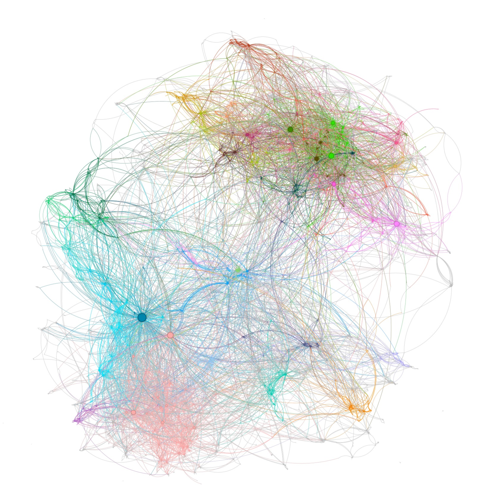
This image displays a highly complex, unlabelled network graph (specifically, a force-directed node-link diagram) rendered against a solid white background. **CRITICAL NOTE:** There is absolutely no text, typography, labels, axes, legends, or explicit numerical data present in this image. Therefore, no factual data tables or exact numerical values can be extracted.
Instead, the image conveys structural and relational information through visual encodings: nodes (circles representing entities), edges (curved lines representing relationships or interactions), node size (representing degree or centrality), and color (representing modularity classes or distinct communities).
### Components/Structure
Because traditional chart axes and legends are absent, the structural components of this visualization are defined by its graphical elements:
* **Nodes (Vertices):** Solid circles of varying diameters. Larger circles indicate a higher number of connections (degree centrality).
* **Edges (Links):** Thin, curved, semi-transparent lines connecting the nodes. The curvature helps distinguish overlapping connections.
* **Color Coding:** Distinct hues (Cyan, Dark Blue, Green, Pink, Orange, Purple) are used to group nodes and their primary edges into clusters, indicating algorithmic community detection.
* **Layout:** The spatial distribution appears to be a force-directed layout, where connected nodes are pulled together (forming dense clusters) and unconnected nodes are pushed apart, utilizing the white space to show relational distance.
### Detailed Analysis (Spatial Grounding & Component Isolation)
To analyze this complex structure, the graph can be segmented into distinct spatial and color-coded regions:
**1. The Center-Left Hub (Cyan/Dark Blue Region)**
* *Visual Trend:* A classic "hub-and-spoke" topology radiating from a single massive point.
* *Details:* Located in the mid-to-lower left quadrant. This region is dominated by a single, prominent **Dark Blue node**, which is visually the largest node in the entire graph. Hundreds of light blue/cyan edges radiate outward from this single point, connecting to a vast array of smaller, peripheral cyan nodes. This cluster has long, sweeping connections reaching across the graph to the top-right and bottom-center clusters.
**2. The Top-Right Agglomeration (Green/Olive/Magenta Region)**
* *Visual Trend:* A highly dense, tightly knit "mesh" topology with multiple medium-sized hubs rather than one dominant center.
* *Details:* Located in the upper right quadrant. This is the most visually dense area of the graph. It contains several distinct, medium-to-large nodes colored bright green, olive green, and dark magenta. The edges here are highly entangled and short, suggesting intense internal connectivity.
**3. The Bottom-Center Base (Pink/Light Red Region)**
* *Visual Trend:* A diffuse but highly interconnected cloud lacking a single dominant hub.
* *Details:* Located at the bottom center of the image. The nodes here are generally small to very small. There is a high density of internal pink/red edges, creating a "cloud" effect. It shares a significant number of bridging edges with the Cyan hub to its left.
**4. Peripheral and Minor Clusters**
* *Orange/Yellow:* Found in two primary locations—a sparse grouping at the top-center (bridging the left and right main clusters) and a smaller, distinct cluster at the bottom-right edge.
* *Purple:* A small, distinct cluster located at the extreme bottom-left edge, connected primarily to the outer edges of the Cyan cluster.
**5. Inter-Cluster Edges (The "Bridges")**
* *Visual Trend:* Long, sweeping arcs crossing the negative (white) space.
* *Details:* While edges within clusters share the cluster's color, the graph features many long, faint, often grey or multi-colored lines connecting distant nodes. A massive bundle of these bridging edges flows between the Center-Left (Cyan) hub and the Top-Right (Green) agglomeration.
### Key Observations
* **Extreme Centrality:** The dark blue node on the left possesses an exceptionally high degree of centrality compared to any other node in the network.
* **Differing Topologies:** The graph demonstrates two distinct types of network behavior simultaneously: a broadcast/influencer model (the left cyan hub) and a community/echo-chamber model (the top-right green mesh).
* **High Modularity:** The distinct separation of colors indicates that the algorithm used to generate this graph found very strong, isolated communities that interact internally much more than they interact externally.
### Interpretation
*Note: Because the graph is unlabelled, this interpretation relies on standard network analysis principles (Peircean abduction) applied to the visual topology.*
* **What the data suggests:** This visualization likely represents a complex system such as a social media network (e.g., Twitter/X retweets or mentions), a biological network (protein-protein interactions), or an IT routing topology.
* **Reading between the lines:**
* If this is a **social network**, the giant Dark Blue node represents a major broadcaster, celebrity, or viral post. It pushes information out to thousands of disconnected users (the cyan cloud). Conversely, the Top-Right Green cluster represents a highly interactive, conversational community where many users are talking directly to one another, rather than just listening to one central figure.
* The long bridging edges between the Cyan and Green clusters represent "weak ties"—individuals who act as conduits of information between two otherwise isolated communities.
* The smaller clusters (Orange, Purple) represent niche sub-communities that are largely isolated from the main flow of the network, interacting only with the extreme periphery of the larger groups.