## Circuit Diagram: Memristor Circuit with Op-Amp Feedback
### Overview
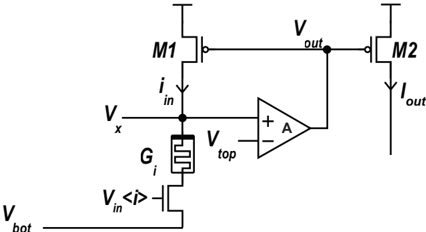
The image depicts an electronic circuit incorporating a memristor, two MOSFET transistors (M1 and M2), and an operational amplifier (op-amp). The circuit appears to be designed to control the output current (I_out) based on the input voltage (V_in) and the memristor's conductance (G_i).
### Components/Axes
* **Transistors:** Two MOSFET transistors labeled M1 and M2.
* **Memristor:** A memristor element labeled G_i.
* **Op-Amp:** An operational amplifier with inputs labeled "+" and "-". The gain is labeled "A".
* **Voltages:** V_bot, V_x, V_in, V_top, V_out.
* **Currents:** i_in, I_out.
### Detailed Analysis
* **Transistor M1:** The drain of M1 is connected to V_x. The source of M1 is connected to the output voltage V_out. The gate of M1 is connected to the power supply.
* **Transistor M2:** The drain of M2 is connected to the output voltage V_out. The source of M2 is connected to ground. The gate of M2 is connected to the power supply.
* **Memristor G_i:** The memristor is connected between the node where V_x and i_in are defined and the drain of another transistor.
* **Input Transistor:** A transistor is connected between the memristor and V_bot. The gate of this transistor is connected to V_in.
* **Op-Amp:** The positive input (+) of the op-amp is connected to the node where V_x and i_in are defined. The negative input (-) of the op-amp is connected to V_top. The output of the op-amp is connected to the output voltage V_out.
### Key Observations
* The circuit uses an op-amp in a feedback configuration, likely to regulate the output voltage or current.
* The memristor's conductance (G_i) plays a crucial role in determining the circuit's behavior.
* The input voltage (V_in) controls the current through the transistor connected to the memristor.
* The output current (I_out) is controlled by the transistor M2.
### Interpretation
This circuit likely functions as a current source or a voltage-controlled resistor, where the memristor's state influences the output. The op-amp provides feedback to maintain a specific relationship between the input voltage, memristor conductance, and output current. The memristor's non-volatile resistance property could be exploited for memory or adaptive circuit applications. The circuit's behavior would depend on the specific characteristics of the memristor and the op-amp's gain.