## Block Diagram: Signal Processing System with Neural Network Component
### Overview
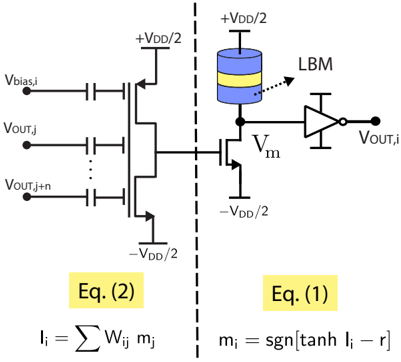
The diagram illustrates a hybrid analog-digital signal processing system combining a neural network-like computation with analog voltage biasing and buffering. The system is divided into two primary functional blocks separated by a dashed line, with labeled equations governing the relationships between components.
### Components/Axes
1. **Left Block (Eq. 2)**:
- **Inputs**:
- `Vblas,i` (bias voltage input)
- `Vout,j` and `Vout,j+n` (sequential output voltages)
- **Equation**:
- `I_i = Σ W_ij * m_j` (weighted sum of inputs, representing neural network neuron activation)
- **Components**:
- Voltage sources: `+VDD/2` and `-VDD/2` (supply rails)
- Buffer/amplifier block labeled "LBM" (likely a linear buffer or operational amplifier)
2. **Right Block (Eq. 1)**:
- **Equation**:
- `m_i = sgn[tanh(I_i - r)]` (sigmoid-like activation function with threshold `r`)
- **Components**:
- Voltage source: `+VDD/2` (biasing input to tanh function)
- Output terminal: `Vout,i` (final processed signal)
### Detailed Analysis
- **Left Block**:
- The summation `I_i = Σ W_ij * m_j` suggests a neural network neuron computing a weighted sum of inputs `m_j` with weights `W_ij`.
- Voltage sources `+VDD/2` and `-VDD/2` provide differential biasing, likely to center the signal around 0V for analog processing.
- The "LBM" block acts as a linear buffer or amplifier, maintaining signal integrity before passing to the right block.
- **Right Block**:
- The activation function `m_i = sgn[tanh(I_i - r)]` introduces non-linearity:
- `tanh(I_i - r)` squashes the input `I_i` (centered at `r`) into a hyperbolic tangent range.
- `sgn()` converts the result to a binary output (`+1` or `-1`), acting as a hard limiter.
- The output `Vout,i` is directly connected to the LBM, indicating analog voltage-level representation of the binary output.
### Key Observations
1. **Signal Flow**:
- Inputs `Vblas,i`, `Vout,j`, and `Vout,j+n` are processed through the left block to compute `I_i`.
- `I_i` is then thresholded and non-linearly transformed in the right block to produce `m_i`, which feeds back into the left block via `Vout,i`.
2. **Biasing**:
- The `+VDD/2` and `-VDD/2` sources ensure symmetric voltage ranges for analog components, critical for accurate tanh function operation.
3. **Feedback Loop**:
- `Vout,i` (output of the right block) is fed back as `Vout,j`/`Vout,j+n` in the left block, suggesting iterative processing or recurrent network behavior.
### Interpretation
This diagram represents a **neuromorphic analog-digital hybrid system**, where:
- The left block implements a **linear neuron** (Eq. 2) with analog voltage inputs and outputs.
- The right block applies a **binary thresholding function** (Eq. 1) to introduce non-linearity, mimicking spiking neuron behavior.
- The **LBM** ensures signal fidelity during analog-to-digital conversion, while the `VDD/2` biasing maintains operational stability.
The system likely models a **spiking neural network (SNN)** or **event-based vision sensor** front-end, where analog voltages represent spike timings, and binary outputs trigger downstream processing. The feedback loop (`Vout,i` → `Vout,j`) implies recurrent connections, enabling temporal memory or adaptive weighting.