# Technical Document Extraction: State Transition Diagram
## 1. Document Overview
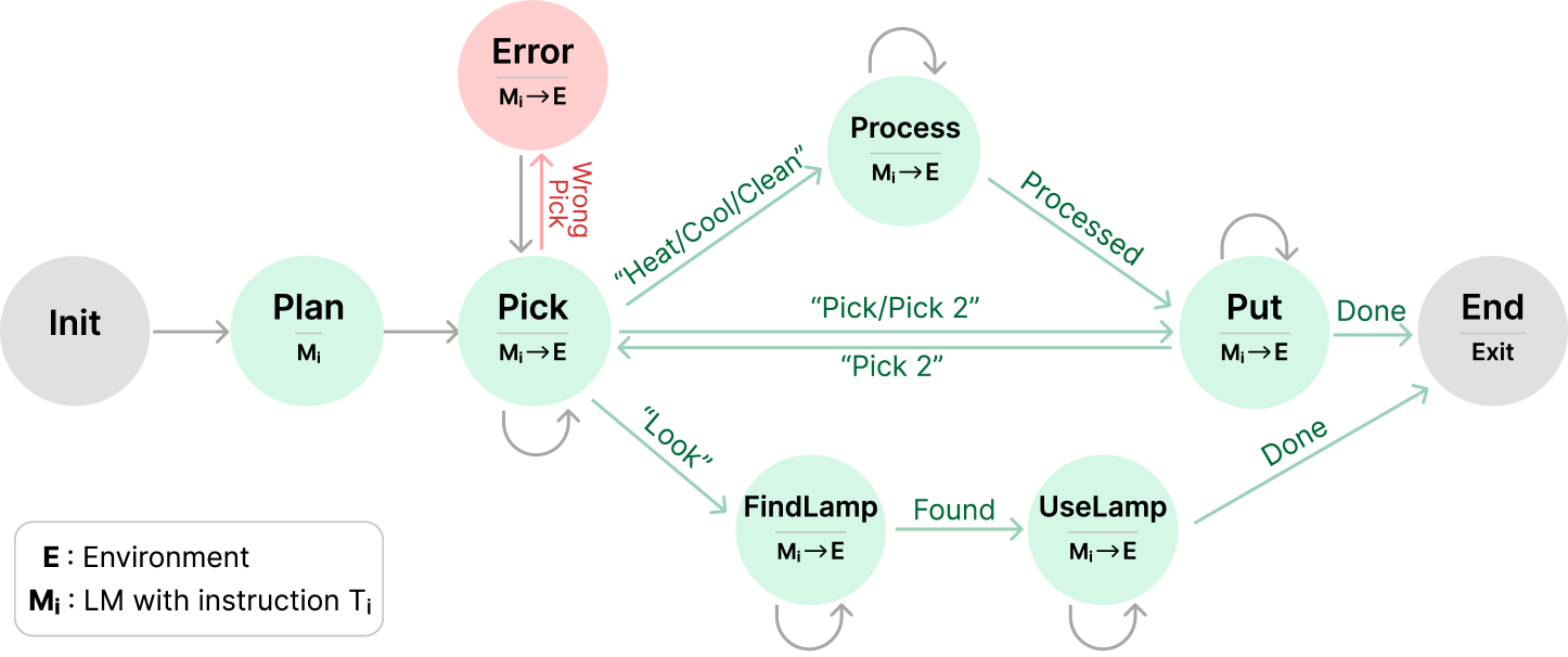
This image is a state transition diagram (finite state machine) illustrating a workflow involving a Language Model ($M_i$) interacting with an Environment ($E$). The diagram uses nodes to represent states and directed arrows to represent transitions triggered by specific actions or conditions.
## 2. Legend and Definitions
Located in the bottom-left corner of the image:
* **E**: Environment
* **$M_i$**: LM (Language Model) with instruction $T_i$
* **$M_i \rightarrow E$**: Indicates an interaction where the Language Model acts upon the Environment.
## 3. Component Analysis (Nodes)
| Node Label | Color | Sub-text | Description |
| :--- | :--- | :--- | :--- |
| **Init** | Grey | (None) | The starting point of the process. |
| **Plan** | Light Green | $M_i$ | Initial planning phase by the LM. |
| **Pick** | Light Green | $M_i \rightarrow E$ | Action state for picking an object. |
| **Error** | Light Red | $M_i \rightarrow E$ | A failure state resulting from an incorrect pick. |
| **Process** | Light Green | $M_i \rightarrow E$ | State for processing an object (e.g., heating/cooling). |
| **Put** | Light Green | $M_i \rightarrow E$ | State for placing an object. |
| **FindLamp** | Light Green | $M_i \rightarrow E$ | Search state for a light source. |
| **UseLamp** | Light Green | $M_i \rightarrow E$ | State for utilizing the light source. |
| **End** | Grey | Exit | The termination point of the process. |
## 4. Transition Logic and Flow
The flow moves generally from left to right, with specific loops and branches based on task requirements.
### A. Initialization and Planning
1. **Init $\rightarrow$ Plan**: Initial transition (Grey arrow).
2. **Plan $\rightarrow$ Pick**: Transition to the first action state (Grey arrow).
### B. The "Pick" Branching Logic
The **Pick** state serves as a central hub with several possible transitions:
* **Self-Loop**: A grey arrow indicates the state can persist or repeat.
* **To Error**: Triggered by **"Wrong Pick"** (Red arrow). The **Error** state has a return arrow back to **Pick** (Grey arrow).
* **To Process**: Triggered by instructions **"Heat/Cool/Clean"** (Green arrow).
* **To Put**: Triggered by instructions **"Pick/Pick 2"** (Green arrow).
* **To FindLamp**: Triggered by instruction **"Look"** (Green arrow).
### C. Processing and Placement Flow
* **Process $\rightarrow$ Process**: Self-loop (Grey arrow).
* **Process $\rightarrow$ Put**: Triggered by the condition **"Processed"** (Green arrow).
* **Put $\rightarrow$ Put**: Self-loop (Grey arrow).
* **Put $\rightarrow$ Pick**: Triggered by instruction **"Pick 2"** (Green arrow), allowing for multi-object tasks.
* **Put $\rightarrow$ End**: Triggered by the condition **"Done"** (Green arrow).
### D. Lighting Utility Flow
* **FindLamp $\rightarrow$ FindLamp**: Self-loop (Grey arrow).
* **FindLamp $\rightarrow$ UseLamp**: Triggered by the condition **"Found"** (Green arrow).
* **UseLamp $\rightarrow$ UseLamp**: Self-loop (Grey arrow).
* **UseLamp $\rightarrow$ End**: Triggered by the condition **"Done"** (Green arrow).
## 5. Summary of Visual Coding
* **Grey Nodes**: Entry and Exit points.
* **Green Nodes**: Active operational states.
* **Red Node**: Failure/Error state.
* **Green Arrows**: Successful transitions or specific command-driven movements.
* **Red Arrows**: Error-driven transitions.
* **Grey Arrows**: Standard flow or state persistence (loops).