# Technical Document Extraction: Flowchart Analysis
## Diagram Overview
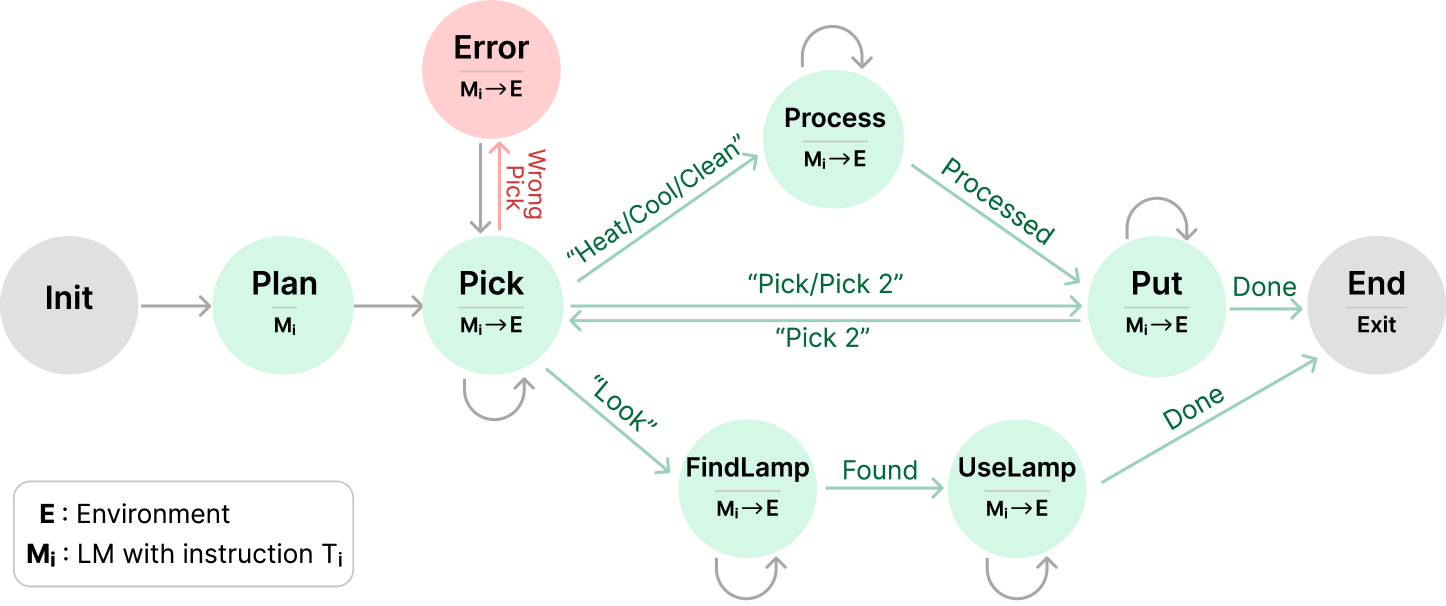
The image depicts a state transition diagram for a task execution system with environmental interaction. The flowchart includes decision nodes, action nodes, error handling, and state transitions. All text is in English.
---
## Key Components and Flow
### 1. Initialization
- **Node**: `Init` (Gray circle)
- **Transition**: `Init → Plan` (Gray arrow)
- **Purpose**: System startup
### 2. Planning Phase
- **Node**: `Plan` (Light green circle)
- **Transition**: `Plan → Pick` (Gray arrow)
- **Instruction**: `M_i → E` (LM with instruction `T_i` to Environment)
### 3. Object Acquisition
- **Node**: `Pick` (Light green circle)
- **Self-loop**: `Pick → Pick` (Gray arrow) labeled `"Look"`
- **Transition to Process**: `Pick → Process` (Green arrow) labeled `"Heat/Cool/Clean"`
- **Transition to FindLamp**: `Pick → FindLamp` (Green arrow) labeled `"Look"`
### 4. Error Handling
- **Node**: `Error` (Red circle)
- **Transition**: `Pick → Error` (Red arrow) labeled `"Wrong Pick"`
- **Transition**: `Error → Pick` (Gray arrow)
### 5. Processing Phase
- **Node**: `Process` (Light green circle)
- **Self-loop**: `Process → Process` (Gray arrow)
- **Transition to Put**: `Process → Put` (Green arrow) labeled `"Processed"`
### 6. Object Utilization
- **Node**: `FindLamp` (Light green circle)
- **Transition**: `FindLamp → UseLamp` (Green arrow) labeled `"Found"`
- **Self-loop**: `UseLamp → UseLamp` (Gray arrow)
### 7. Completion Phase
- **Node**: `Put` (Light green circle)
- **Transition**: `Put → End` (Green arrow) labeled `"Done"`
- **Self-loop**: `Put → Put` (Gray arrow)
### 8. Termination
- **Node**: `End` (Gray circle)
- **Transition**: `End → Exit` (Gray arrow)
---
## Legend and Notation
- **E**: Environment
- **M_i**: LM with instruction `T_i`
- **Transition Syntax**: `Source → Target` (Arrow color indicates transition type)
- Gray: System flow
- Green: Successful action
- Red: Error condition
---
## Spatial Grounding
- **Legend Position**: Bottom-left quadrant
- **Node Colors**:
- Gray: System states (`Init`, `End`)
- Light Green: Operational states (`Plan`, `Pick`, `Process`, `Put`, `FindLamp`, `UseLamp`)
- Red: Error state
---
## Flowchart Logic
1. **Normal Execution Path**:
`Init → Plan → Pick → Process → Put → End`
2. **Alternative Paths**:
- **Search Loop**: `Pick → FindLamp → UseLamp → Put`
- **Error Recovery**: `Pick → Error → Pick`
3. **Conditional Transitions**:
- `"Pick 2"` (Double object acquisition)
- `"Heat/Cool/Clean"` (Environmental processing)
---
## Critical Observations
1. **State Persistence**: All operational nodes (`Plan`, `Pick`, etc.) maintain self-loops for iterative processing.
2. **Error Handling**: Explicit error state with dedicated transition from `Pick` node.
3. **Environmental Interaction**: All actions (`Pick`, `Process`, `UseLamp`) involve `M_i → E` transitions.
4. **Completion Criteria**: `"Done"` transition from `Put` node triggers system exit.
---
## Diagram Structure