\n
## Diagram: System Architecture for Detecting Inconsistent Instructions
### Overview
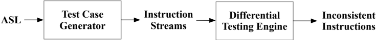
The image depicts a system architecture diagram illustrating a process for identifying inconsistent instructions. The diagram shows a sequential flow of data through four distinct components, starting with an input labeled "ASL" and culminating in an output labeled "Inconsistent Instructions".
### Components/Axes
The diagram consists of four rectangular blocks, each representing a component of the system. These are arranged horizontally from left to right, connected by arrows indicating the flow of data. The components are:
1. **ASL:** The input to the system.
2. **Test Case Generator:** Transforms the ASL input.
3. **Instruction Streams:** Receives output from the Test Case Generator.
4. **Differential Testing Engine:** Processes the Instruction Streams.
5. **Inconsistent Instructions:** The final output of the system.
### Detailed Analysis or Content Details
The diagram shows a linear process flow:
1. **ASL** (Approximate position: far left) serves as the initial input.
2. An arrow points from **ASL** to the **Test Case Generator** (Approximate position: left-center).
3. The **Test Case Generator** produces **Instruction Streams** (Approximate position: center-left).
4. An arrow points from **Instruction Streams** to the **Differential Testing Engine** (Approximate position: center).
5. The **Differential Testing Engine** outputs **Inconsistent Instructions** (Approximate position: right-center).
6. An arrow points from the **Differential Testing Engine** to **Inconsistent Instructions** (Approximate position: far right).
There are no numerical values or axes present in this diagram. It is a purely conceptual representation of a system.
### Key Observations
The diagram highlights a pipeline for detecting inconsistencies in instructions. The system appears to be designed to take a formal specification (ASL) and generate test cases to identify situations where instructions conflict or lead to unexpected behavior.
### Interpretation
This diagram illustrates a system designed for verifying the consistency of instructions, likely within a software or AI context. The "ASL" input suggests a formal language used to define the desired behavior. The "Test Case Generator" creates scenarios to test the instructions, and the "Differential Testing Engine" compares the results to identify inconsistencies. The final output, "Inconsistent Instructions," indicates the system's ability to flag problematic instructions. The diagram suggests a focus on rigorous testing and validation to ensure reliable and predictable system behavior. The system is likely used in the development or evaluation of large language models or other instruction-following systems.