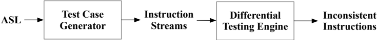
## [Diagram]: ASL Instruction Testing Pipeline Flowchart
### Overview
The image displays a linear, left-to-right process flow diagram illustrating a pipeline for testing instructions derived from an "ASL" source. The diagram consists of four main textual components connected by three directional arrows, indicating a sequential workflow.
### Components/Axes
The diagram is composed of the following elements, positioned horizontally from left to right:
1. **Input Label (Far Left):** The text "ASL" is positioned at the start of the flow.
2. **First Process Block (Left-Center):** A rectangular box containing the text "Test Case Generator".
3. **Second Process Block (Center):** A rectangular box containing the text "Instruction Streams".
4. **Third Process Block (Right-Center):** A rectangular box containing the text "Differential Testing Engine".
5. **Output Label (Far Right):** The text "Inconsistent Instructions" is positioned at the end of the flow.
**Flow Direction:** Three simple, right-pointing arrows connect the elements in sequence:
* An arrow points from "ASL" to the "Test Case Generator" box.
* An arrow points from the "Test Case Generator" box to the "Instruction Streams" box.
* An arrow points from the "Instruction Streams" box to the "Differential Testing Engine" box.
* An arrow points from the "Differential Testing Engine" box to "Inconsistent Instructions".
### Detailed Analysis
The diagram defines a clear, unidirectional pipeline:
1. **Stage 1 - Input:** The process begins with "ASL" (likely an acronym for a specification or language, such as *Architecture Specification Language*).
2. **Stage 2 - Generation:** The "ASL" input is fed into a "Test Case Generator," which presumably creates test cases based on the specification.
3. **Stage 3 - Intermediate Output:** The generator produces "Instruction Streams," which are sequences of instructions to be tested.
4. **Stage 4 - Analysis:** These instruction streams are processed by a "Differential Testing Engine." This component likely compares the behavior or output of the instructions under different conditions or against a reference model.
5. **Stage 5 - Final Output:** The final result of the pipeline is the identification of "Inconsistent Instructions," which are the faults or discrepancies found by the testing engine.
### Key Observations
* The diagram is purely conceptual and contains no numerical data, metrics, or performance indicators.
* The structure is strictly linear with no feedback loops or conditional branches shown.
* The terminology suggests a focus on formal verification or automated testing of instruction set architectures or similar computational models.
### Interpretation
This diagram outlines a methodology for automated verification. The **ASL** serves as the authoritative source of truth (a specification). The pipeline's purpose is to automatically generate test cases from this specification, execute them as instruction streams, and then use differential testing—a powerful technique that compares results from two or more implementations or execution environments—to pinpoint instructions that behave inconsistently. The ultimate goal is to find bugs or ambiguities in a processor design, compiler, or interpreter by revealing where its execution diverges from the expected behavior defined by the ASL. The flow emphasizes a systematic, automated approach to uncovering errors in complex computational systems.