## Diagram: Quantum Annealing vs. Simulated Annealing Conceptual Relationship
### Overview
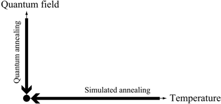
The image is a conceptual diagram illustrating the relationship between two optimization methods—Quantum Annealing and Simulated Annealing—and their associated domains. It uses a simple two-axis layout with directional arrows to show how each method originates from a distinct conceptual space and converges toward a common point.
### Components/Axes
The diagram consists of two perpendicular axes forming an L-shape, with text labels and directional arrows.
1. **Vertical Axis (Left Side):**
* **Label:** "Quantum annealing" (written vertically, reading from bottom to top).
* **Direction:** A thick black arrow points **downward** along this axis.
* **Origin Label:** At the top of this axis, the text "Quantum field" is placed.
2. **Horizontal Axis (Bottom):**
* **Label:** "Simulated annealing" (written horizontally).
* **Direction:** A thick black arrow points **leftward** along this axis.
* **Origin Label:** At the right end of this axis, the text "Temperature" is placed.
3. **Convergence Point:**
* The downward arrow from "Quantum annealing" and the leftward arrow from "Simulated annealing" meet at a single, solid black dot located at the bottom-left corner of the diagram (the intersection of the two axes).
### Detailed Analysis
* **Spatial Grounding:** The "Quantum field" label is positioned top-center relative to the vertical axis. The "Temperature" label is positioned center-right relative to the horizontal axis. The convergence dot is at the absolute bottom-left of the graphical elements.
* **Flow and Direction:** The diagram establishes two distinct pathways:
1. A vertical flow from the abstract "Quantum field" down through the process of "Quantum annealing."
2. A horizontal flow from the classical parameter "Temperature" leftward through the process of "Simulated annealing."
* **Text Transcription:** All text is in English. The precise labels are: "Quantum field", "Quantum annealing", "Simulated annealing", and "Temperature".
### Key Observations
* The diagram is purely conceptual and contains **no numerical data, scales, or quantitative values**. It is a schematic, not a chart.
* The use of thick, bold arrows emphasizes directionality and process flow.
* The convergence at a single point is the central visual metaphor, suggesting a common goal, outcome, or operational point reached by both methods.
* The layout is asymmetric, with the vertical axis on the left and the horizontal axis on the bottom, creating a focused point of interest in the lower-left quadrant.
### Interpretation
This diagram visually hypothesizes a relationship between quantum and classical annealing techniques. It suggests that:
1. **Distinct Origins:** Quantum annealing is fundamentally rooted in or driven by principles of a "Quantum field," while simulated annealing is classically governed by the parameter of "Temperature."
2. **Convergent Process:** Despite their different foundations, both processes are depicted as directional pathways (annealing) that lead to the same destination or solution state (the black dot). This implies that for a given problem, both methods might be applicable or aim for a similar optimal result.
3. **Conceptual Mapping:** The diagram serves as a high-level conceptual map, likely used to frame a discussion comparing the two optimization strategies. It abstracts away all technical details to highlight their philosophical or methodological origins and their potential equivalence in outcome. The lack of data indicates its purpose is to illustrate a relationship or model, not to present empirical results.