## Diagram: Correspondence Filtering and Iterative Decoding Process
### Overview
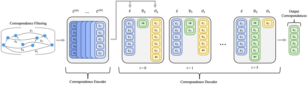
The image depicts a multi-stage algorithmic pipeline designed for "Correspondence Filtering" and iterative "Correspondence Decoding." The process begins with a raw set of correspondences, which are then encoded and passed through a decoder that iteratively refines the selection of correspondences over time steps ($t=0$ to $t=5$), ultimately producing a filtered set of "Output Correspondences."
### Components/Axes
The diagram is organized horizontally from left to right, divided into four primary functional regions:
1. **Correspondence Filtering (Far Left):** A graph-based representation of input correspondences ($c_1$ through $c_5$).
2. **Correspondence Encoder (Middle-Left):** A block containing the input representation $c^{(0)} \dots c^{(N)}$, featuring a stack of blue boxes labeled $c_1$ through $c_5$.
3. **Correspondence Decoder (Center):** An iterative process block labeled with time steps $t=0$, $t=1$, and $t=5$. It utilizes three types of containers:
* **Blue Boxes ($\mathcal{E}$):** Represent the encoded features.
* **Green Boxes ($\mathcal{D}_t$):** Represent the decoder state/filtering mechanism at time $t$.
* **Yellow Boxes ($\mathcal{O}_t$):** Represent the output/selection state at time $t$.
4. **Output Correspondences (Far Right):** The final result.