## Technical Diagram: Correspondence Processing Pipeline
### Overview
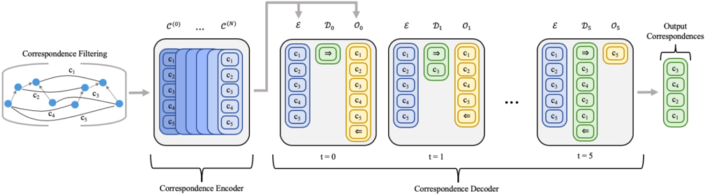
The image illustrates a multi-stage pipeline for processing and refining correspondences, likely from a computer vision or machine learning context. The flow moves left-to-right through three main stages: **Correspondence Filtering**, **Correspondence Encoder**, and **Correspondence Decoder**. The diagram uses color-coding (blue, green, yellow) and symbolic notation to represent data structures and transformations over discrete time steps.
### Components/Axes
The diagram is organized into three primary horizontal sections:
1. **Left Section: Correspondence Filtering**
* **Label:** "Correspondence Filtering" (top-left).
* **Visual:** A network graph with 5 blue circular nodes. Directed edges (arrows) connect these nodes, labeled `c₁`, `c₂`, `c₃`, `c₄`, and `c₅`. This represents an initial set of raw or noisy correspondences.
2. **Middle Section: Correspondence Encoder**
* **Label:** "Correspondence Encoder" (bottom-center).
* **Visual:** A stack of `N+1` layers, labeled `C⁽⁰⁾` through `C⁽ᴺ⁾` at the top. Each layer is a blue rectangle containing a vertical column of 5 elements, labeled `c₁` through `c₅` from top to bottom. An arrow points from the filtering stage to this encoder block.
3. **Right Section: Correspondence Decoder**
* **Label:** "Correspondence Decoder" (bottom-center, spanning the decoder steps).
* **Visual:** A sequence of processing steps at discrete time indices `t = 0`, `t = 1`, and `t = 5` (with `...` indicating intermediate steps). Each time step is a gray box containing three vertical columns:
* **Column `E` (Left, Blue):** Contains a fixed set of 5 elements, `c₁` through `c₅`.
* **Column `D_t` (Middle, Green):** Represents the decoder state at time `t`. Its contents change over time.
* **Column `O_t` (Right, Yellow):** Represents the output or selection at time `t`. Its contents also change.
* **Final Output:** An arrow points from the `t=5` decoder box to a final green column labeled "Output Correspondences," containing elements `c₁`, `c₂`, `c₃`, and `c₄`.
### Detailed Analysis
**Stage 1: Correspondence Filtering**
* Input: A graph of 5 nodes with directed edges representing initial correspondences `c₁` to `c₅`.
* Output: The filtered set of correspondences is passed to the encoder.
**Stage 2: Correspondence Encoder**
* Structure: A stack of `N+1` layers (`C⁽⁰⁾` to `C⁽ᴺ⁾`).
* Data: Each layer processes the same set of 5 correspondences (`c₁`-`c₅`), suggesting a deep or iterative encoding process that transforms the initial graph into a latent representation.
**Stage 3: Correspondence Decoder (Time-Series Analysis)**
* **t=0:**
* `D₀` (Green): Contains a right-pointing arrow (`⇒`) and `c₃`.
* `O₀` (Yellow): Contains `c₁`, `c₂`, `c₃`, `c₄`, `c₅`, and a left-pointing arrow (`⇐`) at the bottom.
* **t=1:**
* `D₁` (Green): Contains a right-pointing arrow (`⇒`) and `c₃`.
* `O₁` (Yellow): Contains `c₁`, `c₂`, `c₃`, `c₄`, `c₅`, and a left-pointing arrow (`⇐`) at the bottom. The state appears unchanged from `t=0`.
* **t=5 (Final Step):**
* `D₅` (Green): Contains a right-pointing arrow (`⇒`), `c₁`, `c₂`, `c₄`, `c₅`, and a left-pointing arrow (`⇐`) at the bottom. The element `c₃` is notably absent from this column.
* `O₅` (Yellow): Contains only `c₃`, which is highlighted with a yellow background.
* **Final Output:** The "Output Correspondences" column (green) lists `c₁`, `c₂`, `c₃`, and `c₄`. The correspondence `c₅` is not included in the final output.
### Key Observations
1. **Color-Coded Data Flow:** Blue represents input/encoded data (`E`, `C` layers). Green represents decoder state/active processing (`D_t`, Output). Yellow represents selected/highlighted output (`O_t`).
2. **Temporal Evolution:** The decoder state (`D_t`) and output (`O_t`) evolve from `t=0` to `t=5`. The key change is the isolation of `c₃` into the output column `O₅` by the final step.
3. **Symbolic Logic:** The arrows (`⇒`, `⇐`) within the decoder columns likely represent operations like "select," "pass," or "attend to." The `⇒` in `D_t` may indicate a forward selection process, while the `⇐` in `O_t` may indicate a backward confirmation or finalization step.
4. **Filtering Outcome:** The pipeline starts with 5 correspondences (`c₁`-`c₅`) and outputs 4 (`c₁`-`c₄`). The correspondence `c₅` is filtered out during the decoding process, as it is present in `E` and early `O_t` but absent from the final "Output Correspondences."
### Interpretation
This diagram depicts an **iterative refinement architecture** for correspondence selection or matching. The **Encoder** transforms a noisy initial graph into a structured latent representation. The **Decoder** then operates over multiple time steps (`t=0` to `t=5`) to progressively select and validate the most reliable correspondences.
The process suggests a **attention-based or recurrent mechanism**. At each step, the decoder (`D_t`) attends to the encoded set (`E`) and maintains an internal state. The output column (`O_t`) shows the current selection hypothesis. The critical action happens between `t=1` and `t=5`, where the system converges on `c₃` as a key correspondence (highlighted in `O₅`) and decides to include `c₁`, `c₂`, and `c₄` in the final output while discarding `c₅`.
The architecture is designed to **resolve ambiguity and filter noise** from initial correspondences. The separation into encoding and decoding stages allows for complex, learned transformations followed by sequential decision-making. The final output is a refined, smaller set of correspondences deemed most consistent or reliable by the model. This is fundamental in tasks like feature matching, stereo vision, or object registration, where initial matches are often erroneous and require robust verification.