## Diagram: Simple Feedforward Neural Network Architecture
### Overview
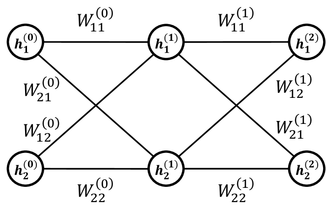
The image displays a schematic diagram of a simple, fully connected feedforward neural network with three layers. The network consists of an input layer (layer 0), a single hidden layer (layer 1), and an output layer (layer 2). Each layer contains two nodes (neurons). Directed connections, represented by lines, link every node in one layer to every node in the subsequent layer. Each connection is labeled with a weight parameter.
### Components/Axes
The diagram is structured into three vertical columns representing the layers:
* **Left Column (Input Layer / Layer 0):** Contains two circular nodes.
* **Center Column (Hidden Layer / Layer 1):** Contains two circular nodes.
* **Right Column (Output Layer / Layer 2):** Contains two circular nodes.
**Node Labels (from top to bottom within each layer):**
* Input Layer: `h₁⁽⁰⁾`, `h₂⁽⁰⁾`
* Hidden Layer: `h₁⁽¹⁾`, `h₂⁽¹⁾`
* Output Layer: `h₁⁽²⁾`, `h₂⁽²⁾`
**Connection Weight Labels:**
The weights are labeled using the notation `Wᵢⱼ⁽ˡ⁾`, where `l` denotes the layer from which the connection originates, `i` is the index of the destination node in the next layer, and `j` is the index of the source node in the current layer.
* **Weights from Input Layer (0) to Hidden Layer (1):**
* Connection from `h₁⁽⁰⁾` to `h₁⁽¹⁾`: `W₁₁⁽⁰⁾` (top horizontal line)
* Connection from `h₁⁽⁰⁾` to `h₂⁽¹⁾`: `W₂₁⁽⁰⁾` (diagonal line sloping down-right)
* Connection from `h₂⁽⁰⁾` to `h₁⁽¹⁾`: `W₁₂⁽⁰⁾` (diagonal line sloping up-right)
* Connection from `h₂⁽⁰⁾` to `h₂⁽¹⁾`: `W₂₂⁽⁰⁾` (bottom horizontal line)
* **Weights from Hidden Layer (1) to Output Layer (2):**
* Connection from `h₁⁽¹⁾` to `h₁⁽²⁾`: `W₁₁⁽¹⁾` (top horizontal line)
* Connection from `h₁⁽¹⁾` to `h₂⁽²⁾`: `W₂₁⁽¹⁾` (diagonal line sloping down-right)
* Connection from `h₂⁽¹⁾` to `h₁⁽²⁾`: `W₁₂⁽¹⁾` (diagonal line sloping up-right)
* Connection from `h₂⁽¹⁾` to `h₂⁽²⁾`: `W₂₂⁽¹⁾` (bottom horizontal line)
### Detailed Analysis
The diagram explicitly defines the complete connectivity and parameterization of a 2-2-2 neural network.
* **Architecture:** 2 input neurons, 2 hidden neurons, 2 output neurons.
* **Total Trainable Parameters:** 8 weights (4 between input-hidden, 4 between hidden-output). No bias terms are shown in this diagram.
* **Data Flow:** The flow is strictly left-to-right (feedforward). Information from the two input nodes (`h⁽⁰⁾`) is transformed by the first set of weights (`W⁽⁰⁾`) to produce activations in the hidden layer (`h⁽¹⁾`). These hidden activations are then transformed by the second set of weights (`W⁽¹⁾`) to produce the final output values (`h⁽²⁾`).
* **Spatial Layout:** The legend (weight labels) is placed directly adjacent to their corresponding connection lines, ensuring clear association. The layout is symmetrical and unambiguous.
### Key Observations
1. **Complete Connectivity:** The network is "fully connected" or "dense," as every node in layer `l` connects to every node in layer `l+1`.
2. **Notation Consistency:** The labeling scheme is systematic and follows a common convention in machine learning literature (`Wᵢⱼ` for weight to node `i` from node `j`).
3. **Absence of Biases:** The diagram does not include bias parameters (`b`), which are typically added to the weighted sum at each neuron in the hidden and output layers. This is a simplification for illustrative purposes.
4. **Activation Functions Not Shown:** The diagram represents the network's structure and parameters but does not specify the non-linear activation functions (e.g., sigmoid, ReLU) applied at the hidden and output nodes.
### Interpretation
This diagram serves as a foundational blueprint for a simple artificial neural network. It visually encodes the mathematical model where the output `h⁽²⁾` is a function of the input `h⁽⁰⁾` through the composition of two linear transformations (weighted sums) parameterized by `W⁽⁰⁾` and `W⁽¹⁾`, typically interleaved with non-linear activation functions.
The **Peircean investigative** reading reveals this as an *icon* (it resembles the structure it represents) and an *index* (the arrows indicate the causal flow of computation). It is a *symbol* because the labels (`h`, `W`) are arbitrary signs whose meaning is defined by convention in the field of neural networks.
The diagram's primary purpose is pedagogical or architectural specification. It abstracts away the numerical values of the weights and the specific activation functions to focus on the topology and the concept of parameterized connections. The clear, symmetrical layout emphasizes the uniformity of the fully connected design. The absence of biases and activation functions suggests this is a high-level schematic meant to introduce the concept of layered, weighted connections before delving into the complete computational graph used in training.