## Neural Network Diagram: Recurrent Network Architecture
### Overview
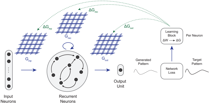
The image presents a diagram of a recurrent neural network architecture. It illustrates the flow of information through different layers, including input neurons, recurrent neurons, and an output unit. The diagram also highlights the learning process, showing how the network adjusts its weights based on the network loss.
### Components/Axes
* **Input Neurons:** A vertical stack of circles labeled "Input Neurons" on the bottom-left.
* **G<sub>inp</sub>:** A grid-like structure representing the input conductance, positioned above and to the right of the input neurons.
* **ΔG<sub>inp</sub>:** A green arrow pointing from the input neurons towards the G<sub>rec</sub> grid, labeled "ΔG<sub>inp</sub>".
* **Recurrent Neurons:** A circular arrangement of nodes within a larger circle, labeled "Recurrent Neurons" at the bottom. Arrows indicate connections between the nodes.
* **G<sub>rec</sub>:** A grid-like structure representing the recurrent conductance, positioned above the recurrent neurons.
* **ΔG<sub>rec</sub>:** A green arrow pointing from the recurrent neurons towards the Learning Block, labeled "ΔG<sub>rec</sub>".
* **G<sub>out</sub>:** A grid-like structure representing the output conductance, positioned to the right of the recurrent neurons.
* **ΔG<sub>out</sub>:** A green arrow pointing from the output neurons towards the Learning Block, labeled "ΔG<sub>out</sub>".
* **Output Unit:** A single oval labeled "Output Unit" at the bottom.
* **Generated Pattern:** A dotted line representing the generated pattern, positioned to the right of the output unit.
* **Network Loss:** A rectangular box labeled "Network Loss" below the Learning Block.
* **Target Pattern:** A solid line representing the target pattern, positioned to the right of the Network Loss.
* **Learning Block:** A rounded rectangle labeled "Learning Block" with the equation "ΔW → ΔG" inside. The text "Per Neuron" is written to the right of the block.
### Detailed Analysis
* **Input Layer:** The input neurons feed into the G<sub>inp</sub> grid.
* **Recurrent Layer:** The recurrent neurons are interconnected, forming a dynamic system.
* **Output Layer:** The output unit receives input from the recurrent layer.
* **Learning Process:** The network loss is calculated by comparing the generated pattern with the target pattern. This loss is then used to adjust the weights (ΔW) in the learning block, which in turn affects the conductances (ΔG).
* **Conductance Grids:** The G<sub>inp</sub>, G<sub>rec</sub>, and G<sub>out</sub> grids likely represent the synaptic conductances between the layers.
* **Feedback Loop:** A curved arrow indicates a feedback loop within the recurrent neurons, suggesting that the output of these neurons influences their own input.
### Key Observations
* The diagram emphasizes the flow of information and the learning process in a recurrent neural network.
* The use of conductance grids (G<sub>inp</sub>, G<sub>rec</sub>, G<sub>out</sub>) suggests a focus on synaptic plasticity.
* The feedback loop within the recurrent layer is a key characteristic of recurrent neural networks, allowing them to process sequential data.
### Interpretation
The diagram illustrates a typical recurrent neural network architecture. The input neurons feed into a recurrent layer, which processes the information and generates an output. The network learns by comparing its output to a target pattern and adjusting its weights accordingly. The conductance grids likely represent the strength of the connections between neurons, which are modified during the learning process. The feedback loop within the recurrent layer allows the network to maintain a memory of past inputs, making it suitable for tasks such as natural language processing and time series analysis. The diagram highlights the key components and processes involved in recurrent neural network learning.