## Diagram: Write Enable Selection and Data Write
### Overview
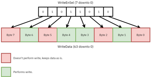
This diagram illustrates the relationship between a write enable selection signal (`WriteEnSel`) and a data write operation on a series of bytes (`WriteData`). The diagram shows how specific bits in `WriteEnSel` control which bytes in `WriteData` are written to.
### Components/Axes
* **WriteEnSel (7 down to 0):** A bitfield consisting of 8 bits, labeled from 7 to 0, positioned at the top of the diagram. The values of these bits are explicitly shown as `0 1 0 1 1 0 1 0`.
* **WriteData (63 down to 0):** A data block representing 8 bytes, labeled from 7 to 0, positioned at the bottom of the diagram.
* **Arrows:** Arrows connect each bit in `WriteEnSel` to a corresponding byte in `WriteData`, indicating the control relationship.
* **Legend:** Located in the bottom-left corner, the legend defines the color coding:
* Red: "Doesn't perform write, keeps data as is."
* Green: "Performs write."
### Detailed Analysis
The diagram shows the following byte-level write enable/disable configuration:
* **Byte 7:** Controlled by `WriteEnSel[7] = 0`. The corresponding byte in `WriteData` is colored red, indicating no write operation is performed.
* **Byte 6:** Controlled by `WriteEnSel[6] = 1`. The corresponding byte in `WriteData` is colored green, indicating a write operation is performed.
* **Byte 5:** Controlled by `WriteEnSel[5] = 0`. The corresponding byte in `WriteData` is colored red, indicating no write operation is performed.
* **Byte 4:** Controlled by `WriteEnSel[4] = 1`. The corresponding byte in `WriteData` is colored green, indicating a write operation is performed.
* **Byte 3:** Controlled by `WriteEnSel[3] = 1`. The corresponding byte in `WriteData` is colored green, indicating a write operation is performed.
* **Byte 2:** Controlled by `WriteEnSel[2] = 0`. The corresponding byte in `WriteData` is colored red, indicating no write operation is performed.
* **Byte 1:** Controlled by `WriteEnSel[1] = 1`. The corresponding byte in `WriteData` is colored green, indicating a write operation is performed.
* **Byte 0:** Controlled by `WriteEnSel[0] = 0`. The corresponding byte in `WriteData` is colored red, indicating no write operation is performed.
### Key Observations
The `WriteEnSel` signal appears to act as a byte-level enable for writing to `WriteData`. A '1' in `WriteEnSel` enables the write for the corresponding byte, while a '0' disables it. The pattern of `WriteEnSel` is `0 1 0 1 1 0 1 0`.
### Interpretation
This diagram demonstrates a mechanism for selectively writing to specific bytes within a larger data block. This is a common technique in hardware design to optimize data transfer and reduce unnecessary writes. The `WriteEnSel` signal provides a flexible way to control which bytes are updated, potentially improving performance and reducing power consumption. The alternating pattern of enabled and disabled bytes suggests a specific data manipulation strategy, possibly related to updating only certain fields within a data structure. The diagram is a clear visual representation of a bitfield controlling a byte-level write operation.