## Mathematical Diagram: Vector Decomposition in a Coordinate System
### Overview
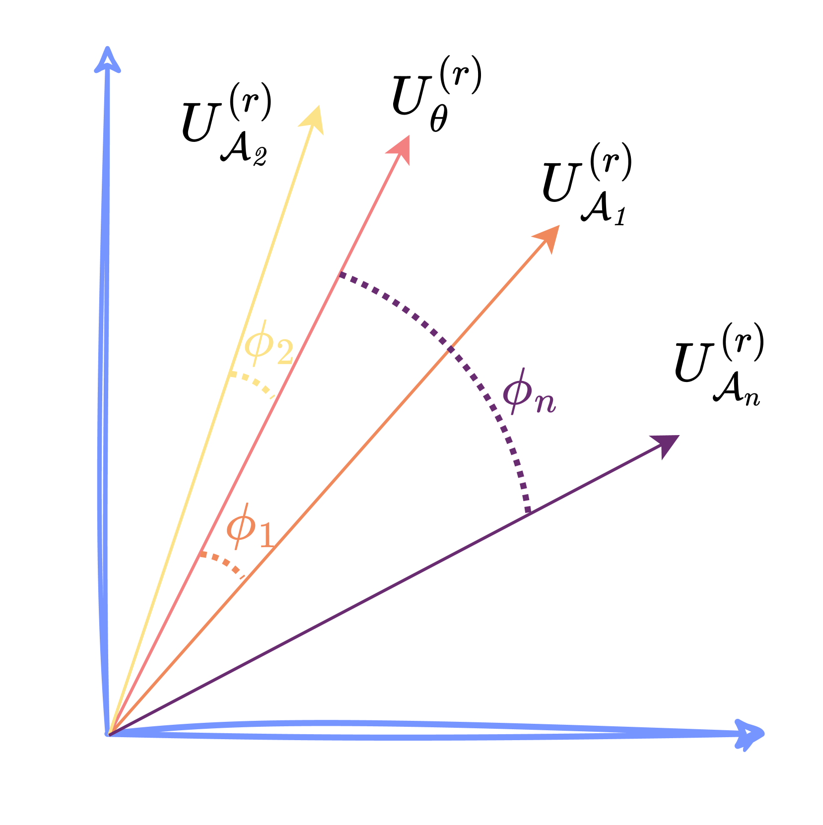
The image is a technical diagram illustrating a set of vectors originating from the origin of a two-dimensional Cartesian coordinate system. It depicts a primary vector and several component vectors, with angles defined between them. The diagram is likely used to explain concepts in vector analysis, coordinate transformations, or signal decomposition.
### Components/Axes
1. **Coordinate System:**
* A standard 2D Cartesian plane is shown.
* **Axes:** Two blue arrows form the axes. The horizontal axis points to the right, and the vertical axis points upward. They are unlabeled but conventionally represent the x and y axes.
* **Origin:** All vectors originate from the intersection point of the axes (0,0).
2. **Vectors (from lowest to highest angle relative to the horizontal axis):**
* **Vector 1 (Blue):** Lies exactly along the positive horizontal axis. It is labeled **`U_{A_n}^{(r)}`**. The label is positioned to the right of the vector's arrowhead.
* **Vector 2 (Purple):** Extends from the origin into the first quadrant at a moderate angle. It is labeled **`U_{A_1}^{(r)}`**. The label is positioned to the right of the vector's arrowhead.
* **Vector 3 (Orange):** Extends from the origin into the first quadrant at a steeper angle than the purple vector. It is labeled **`U_{θ}^{(r)}`**. The label is positioned above and to the right of the vector's arrowhead.
* **Vector 4 (Pink):** Extends from the origin into the first quadrant at a steeper angle than the orange vector. It is labeled **`U_{A_2}^{(r)}`**. The label is positioned above and to the left of the vector's arrowhead.
* **Vector 5 (Yellow):** Extends from the origin into the first quadrant at the steepest angle shown. It is labeled **`U_{A_2}^{(r)}`**. The label is positioned to the left of the vector's arrowhead.
3. **Angles:**
* **Angle φ₁ (phi_1):** Marked by a dashed orange arc between the **purple vector (`U_{A_1}^{(r)}`)** and the **orange vector (`U_{θ}^{(r)}`)**. The label **`φ₁`** is placed near the arc.
* **Angle φ₂ (phi_2):** Marked by a dashed yellow arc between the **orange vector (`U_{θ}^{(r)}`)** and the **yellow vector (`U_{A_2}^{(r)}`)**. The label **`φ₂`** is placed near the arc.
* **Angle φₙ (phi_n):** Marked by a dashed purple arc between the **purple vector (`U_{A_1}^{(r)}`)** and the **blue vector (`U_{A_n}^{(r)}`)**. The label **`φₙ`** is placed near the arc.
### Detailed Analysis
* **Vector Arrangement:** The vectors are arranged in a fan-like pattern, all starting from the origin. Their order by increasing angle from the horizontal axis is: Blue (`U_{A_n}^{(r)}`), Purple (`U_{A_1}^{(r)}`), Orange (`U_{θ}^{(r)}`), Pink (`U_{A_2}^{(r)}`), Yellow (`U_{A_2}^{(r)}`).
* **Notation:** All vector labels follow the pattern `U` with a subscript and a superscript `(r)`. The subscripts are `A_n`, `A_1`, `θ`, and `A_2`. The subscript `A_2` appears twice (on the pink and yellow vectors), which may indicate a labeling error or that they represent similar components in different contexts.
* **Angle Definitions:**
* `φ₁` defines the angular separation between the `U_{A_1}^{(r)}` and `U_{θ}^{(r)}` vectors.
* `φ₂` defines the angular separation between the `U_{θ}^{(r)}` and `U_{A_2}^{(r)}` (yellow) vectors.
* `φₙ` defines the angular separation between the `U_{A_1}^{(r)}` and `U_{A_n}^{(r)}` vectors. This angle spans across the orange vector.
### Key Observations
1. **Central Reference Vector:** The orange vector labeled `U_{θ}^{(r)}` appears to be a central or reference vector, as the defined angles `φ₁` and `φ₂` are measured from it to its immediate neighbors.
2. **Potential Label Duplication:** The subscript `A_2` is used for two distinct vectors (pink and yellow). This is unusual and could be a diagrammatic error, or it might imply these vectors belong to the same class or set (`A_2`) but have different magnitudes or specific roles.
3. **Angle `φₙ` Scope:** The angle `φₙ` is defined between the first (`U_{A_1}^{(r)}`) and last (`U_{A_n}^{(r)}`) vectors in the sequence, suggesting it may represent a total or cumulative angular span.
4. **Color Coding:** Each vector and its associated angle arc (where applicable) share a color, aiding in visual association: Purple vector with `φₙ` arc, Orange vector with `φ₁` arc, Yellow vector with `φ₂` arc.
### Interpretation
This diagram visually represents the decomposition of a vector space or the relationship between multiple directional components. The notation `U^{(r)}` often denotes a unit vector or a component in a specific coordinate system (e.g., radial in polar coordinates).
* **Conceptual Model:** It likely illustrates a scenario where a primary direction or signal (perhaps represented by `U_{θ}^{(r)}`) is being analyzed in relation to other basis vectors (`U_{A_1}^{(r)}`, `U_{A_2}^{(r)}`, `U_{A_n}^{(r)}`). The angles `φ` quantify the angular deviation or phase difference between these components.
* **Possible Contexts:** This could be from fields like:
* **Physics/Engineering:** Representing force components, electromagnetic field directions, or phasor diagrams in AC circuit analysis.
* **Signal Processing:** Showing the direction of arrival of signals or components in a beamforming array.
* **Mathematics:** Illustrating a change of basis in a vector space or the geometry of vector projections.
* **The "n" Subscript:** The use of `A_n` suggests a generalization to an arbitrary number of components, with `A_1` and `A_2` being specific instances. The diagram shows a finite set (n=3 for the A-subscripted vectors) for clarity.
* **Ambiguity:** Without accompanying text, the exact physical or mathematical meaning of the symbols (`U`, `A`, `θ`, `r`) is open to interpretation. The diagram's primary purpose is to convey geometric relationships—angles and relative orientations—between the defined vectors.