# Technical Diagram Analysis
## Overview
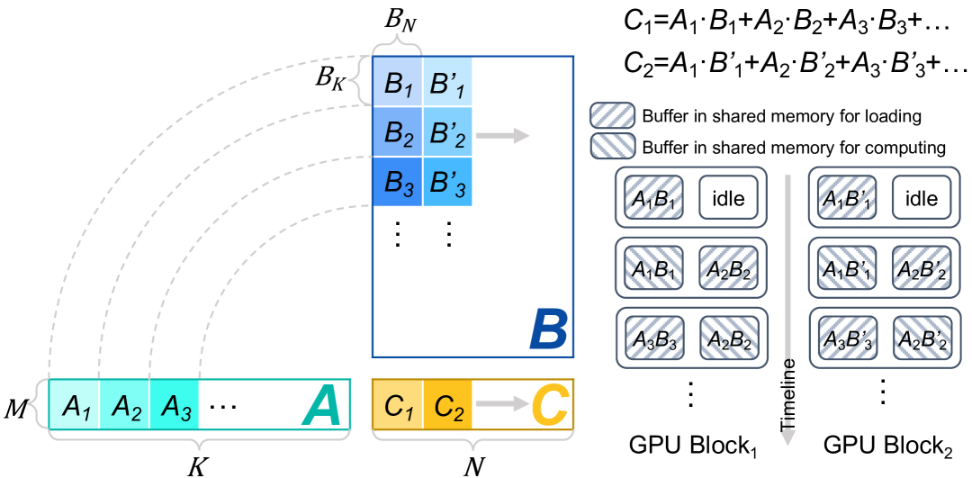
The diagram illustrates a GPU-based matrix multiplication process with shared memory buffers. It shows data flow from input matrices through computational blocks to output storage.
## Key Components
### Matrices
1. **Matrix M** (Input A)
- Elements: A₁, A₂, A₃, ..., A
- Color: Teal (#008080)
- Position: [x=0, y=0] to [x=K, y=0]
2. **Matrix B** (Input B)
- Elements: B₁, B₂, B₃, ..., B_N
- Color: Blue (#0000FF)
- Position: [x=K, y=0] to [x=N, y=0]
3. **Matrix C** (Output)
- Elements: C₁, C₂, ..., C
- Color: Orange (#FFA500)
- Position: [x=N, y=0] to [x=?, y=0]
### GPU Architecture
1. **GPU Block 1**
- **Loading Buffer**: Striped pattern (A₁B₁, A₂B₂, A₃B₃)
- **Computing Buffer**: Striped pattern (A₁B₁', A₂B₂', A₃B₃')
- **Idle Sections**: White blocks labeled "idle"
- **Timeline**: Left-to-right sequence
2. **GPU Block 2**
- **Loading Buffer**: Striped pattern (A₁B₁', A₂B₂', A₃B₃')
- **Computing Buffer**: Striped pattern (A₁B₁'', A₂B₂'', A₃B₃'')
- **Idle Sections**: White blocks labeled "idle"
- **Timeline**: Right-to-left sequence
## Computation Flow
1. **Data Loading Phase**
- Matrices A and B are loaded into shared memory buffers
- Buffer pattern: `A_iB_i` → `A_iB_i'` → `A_iB_i''`
2. **Computation Phase**
- Matrix multiplication occurs in parallel blocks
- Result accumulation: `C = A₁·B₁ + A₂·B₂ + A₃·B₃ + ...`
3. **Output Storage**
- Final results stored in matrix C
- Color transition: Teal → Blue → Orange
## Mathematical Representation
- **C₁ Calculation**:
`C₁ = A₁·B₁ + A₂·B₂ + A₃·B₃ + ...`
- **C₂ Calculation**:
`C₂ = A₁·B₁' + A₂·B₂' + A₃·B₃' + ...`
## Spatial Analysis
- **Legend Position**: Not explicitly shown (assumed top-right)
- **Color Consistency Check**:
- All A elements: Teal (#008080)
- All B elements: Blue (#0000FF)
- All C elements: Orange (#FFA500)
## Trend Verification
- **Data Flow**: Left-to-right progression through GPU blocks
- **Computation Pattern**: Striped buffers indicate active computation phases
- **Idle Periods**: White blocks show non-computational intervals
## Missing Elements
- No explicit numerical data points or heatmap values present
- No secondary y-axis or colorbar legend
- No textual annotations beyond component labels
## Conclusion
This diagram demonstrates a parallel matrix multiplication algorithm optimized for GPU architecture, utilizing shared memory buffers for efficient data loading and computation. The process involves three main phases: data loading, parallel computation, and result storage, with explicit timing relationships between GPU blocks.