## Diagram: Restricted Boltzmann Machine (RBM) Architecture
### Overview
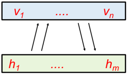
The image depicts a simplified architecture of a Restricted Boltzmann Machine (RBM). It shows two layers: a visible layer (v) and a hidden layer (h), with connections between them. The diagram illustrates the probabilistic connections between the visible units and the hidden units.
### Components/Axes
* **Top Layer (Visible Layer):** A blue rectangle labeled with "v1" on the left, "vn" on the right, and "..." in the middle.
* **Bottom Layer (Hidden Layer):** A green rectangle labeled with "h1" on the left, "hm" on the right, and "..." in the middle.
* **Connections:** Arrows pointing from the hidden layer to the visible layer and from the visible layer to the hidden layer.
### Detailed Analysis or ### Content Details
* **Visible Layer:** The visible layer consists of 'n' units, denoted as v1 to vn.
* **Hidden Layer:** The hidden layer consists of 'm' units, denoted as h1 to hm.
* **Connections:** The arrows indicate bidirectional connections between the visible and hidden layers. Specifically, there are arrows from h1 to v1 and vn, and arrows from v1 and vn to hm.
### Key Observations
* The diagram shows a bipartite graph structure, where connections exist only between the visible and hidden layers, and not within each layer.
* The "..." notation indicates that there are multiple units in each layer, but only the first and last units are explicitly labeled.
### Interpretation
The diagram illustrates the basic architecture of an RBM, which is a generative stochastic neural network. The visible layer represents the input data, while the hidden layer learns to extract features from the input. The bidirectional connections allow the RBM to learn a probability distribution over the input data. The absence of connections within each layer is a key characteristic of RBMs, simplifying the learning process. The diagram highlights the relationship between the visible and hidden units and the flow of information between them.