## Diagram: Numbered Node Network with Directional Arrows
### Overview
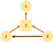
The image displays a simple directed graph or flowchart consisting of four numbered nodes connected by colored arrows. The diagram appears to represent a process, hierarchy, or relationship flow between distinct entities labeled 1 through 4.
### Components/Axes
* **Nodes:**
* **Node 1:** A circle located at the top-center of the diagram.
* **Node 2:** A square located at the center of the diagram.
* **Node 3:** A circle located at the bottom-left of the diagram.
* **Node 4:** A circle located at the bottom-right of the diagram.
* **Arrows (Connections):**
* An **orange arrow** points from Node 2 (center square) upward to Node 1 (top circle).
* An **orange arrow** points from Node 2 (center square) leftward to Node 3 (bottom-left circle).
* An **orange arrow** points from Node 2 (center square) rightward to Node 4 (bottom-right circle).
* A **brown arrow** points from Node 4 (bottom-right circle) leftward to Node 3 (bottom-left circle).
### Detailed Analysis
The diagram's structure is hierarchical and cyclical.
1. **Central Hub:** Node 2 (the square) acts as a central hub or decision point. It has three outgoing connections (orange arrows) to all other nodes.
2. **Terminal Node:** Node 1 (top circle) is a terminal point, receiving a connection only from Node 2.
3. **Sub-Process/Cycle:** Nodes 3 and 4 form a sub-process or cycle at the base. Node 2 feeds into both. Node 4 then feeds into Node 3 via a brown arrow, creating a directional flow from 4 to 3. Node 3 has no outgoing connections shown.
### Key Observations
* **Shape Differentiation:** Node 2 is uniquely represented as a square, while Nodes 1, 3, and 4 are circles. This likely signifies a difference in function or type (e.g., a process step vs. a state or entity).
* **Color-Coded Arrows:** The arrows from the central Node 2 are all orange, suggesting a uniform type of relationship or action originating from it. The arrow from Node 4 to Node 3 is brown, indicating a different type of relationship or a subsequent step in a sequence.
* **Asymmetric Flow:** The flow is not symmetrical. While Node 2 connects to all, the connection between the lower nodes is only one-way (4 → 3).
### Interpretation
This diagram most likely models a simple system or workflow. The central square (Node 2) could represent a controller, manager, or primary process that initiates actions or distributes tasks to three components (Nodes 1, 3, and 4). The brown arrow from Node 4 to Node 3 suggests a dependency, handoff, or sequential step where the output or state of Node 4 influences Node 3. Node 1 appears to be an endpoint or a separate branch of the process that does not feed back into the lower cycle.
The absence of a return path from Node 1 or Node 3 back to Node 2 implies this is not a fully closed-loop system but rather a directed flow with a terminal point (Node 1) and a linear sub-sequence (4 → 3). The diagram effectively communicates structure, directionality, and categorical differences (via shape and color) without additional textual labels.