## Diagram: Communication Network Architecture with Policy Enforcement
### Overview
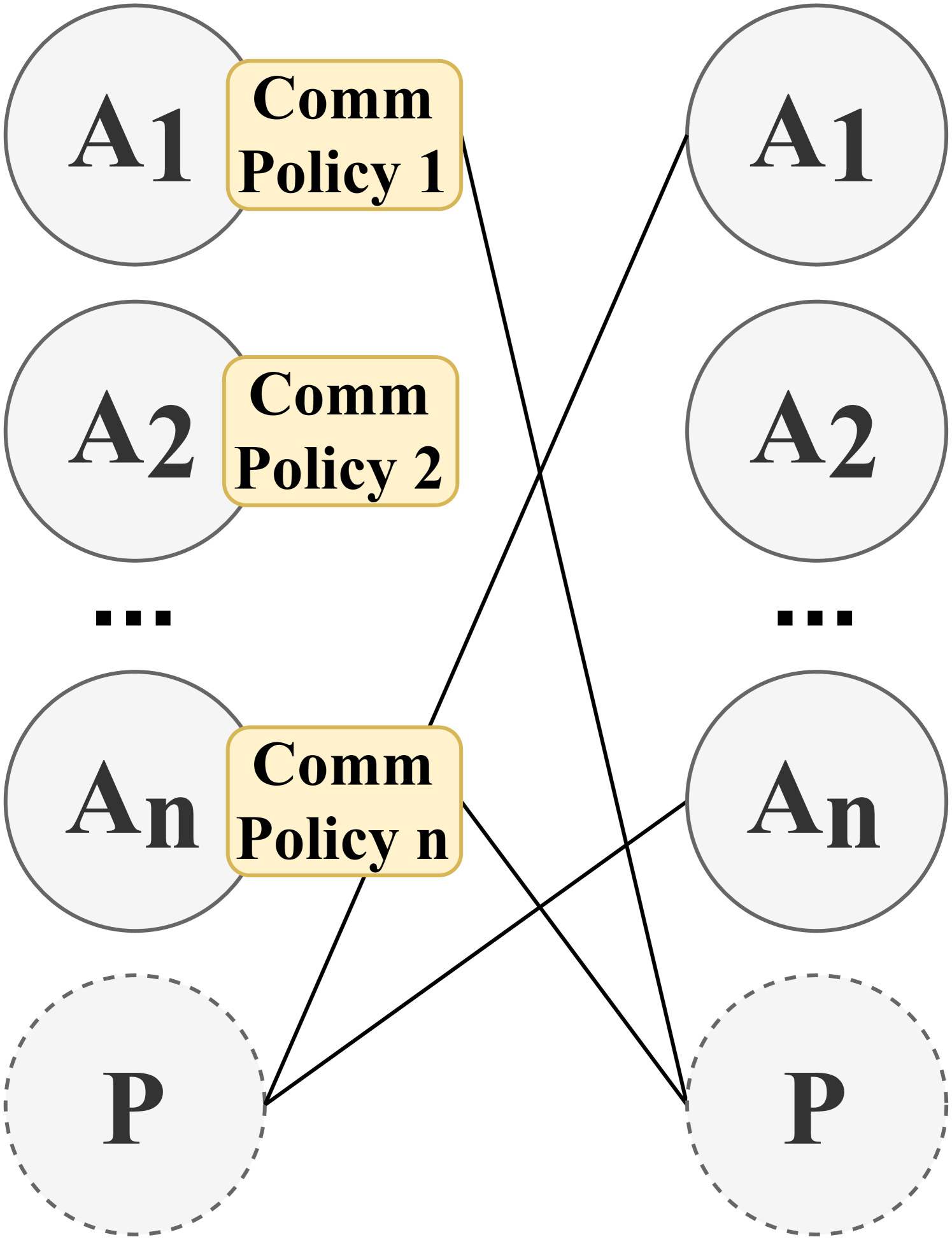
The diagram illustrates a symmetrical communication network architecture with multiple nodes labeled A1 to An on both the left and right sides, connected to a central node labeled P at the bottom. Each connection between nodes is annotated with "Comm Policy" labels (e.g., "Comm Policy 1," "Comm Policy 2," ..., "Comm Policy n"), suggesting policy-driven interactions. Solid lines connect nodes across the diagram, while dotted lines link the central node P to all A nodes.
---
### Components/Axes
1. **Nodes**:
- **Left/Right Nodes**: Labeled A1, A2, ..., An (repeated symmetrically on both sides).
- **Central Node**: Labeled P (dashed outline, positioned at the bottom).
2. **Connections**:
- **Solid Lines**: Connect A nodes across the diagram (e.g., A1 ↔ A1, A2 ↔ A2, ..., An ↔ An).
- **Dotted Lines**: Connect the central node P to all A nodes (A1, A2, ..., An).
3. **Policy Labels**:
- "Comm Policy 1," "Comm Policy 2," ..., "Comm Policy n" are attached to solid lines, indicating policy-specific rules for each connection.
---
### Detailed Analysis
- **Node Symmetry**: The left and right sides mirror each other, with identical labels (A1 to An) and connections. This suggests redundancy, load balancing, or mirrored subsystems.
- **Central Node (P)**: Positioned at the bottom with a dashed outline, P acts as a hub or gateway, connected to all A nodes via dotted lines. This implies P may enforce global policies or aggregate data.
- **Policy Enforcement**: Each solid-line connection between A nodes has a unique "Comm Policy" label, indicating granular control over data flow or permissions between specific nodes.
- **Line Types**: Solid lines (policy-specific) vs. dotted lines (central hub connections) may differentiate between peer-to-peer communication and centralized governance.
---
### Key Observations
1. **Policy Granularity**: Each A node pair (e.g., A1 ↔ A1) has a distinct communication policy, suggesting tailored rules for different interactions.
2. **Centralized Control**: The central node P’s connections to all A nodes imply it may act as a policy enforcer or data intermediary.
3. **Symmetry**: The mirrored A node structure could represent redundancy, failover mechanisms, or parallel processing subsystems.
---
### Interpretation
This diagram likely represents a distributed system where:
- **Nodes (A1-An)** are endpoints or subsystems with defined roles.
- **Central Node (P)** serves as a policy enforcement point or data aggregator.
- **Communication Policies** govern interactions between nodes, ensuring compliance, security, or resource allocation.
- **Symmetry** suggests a design prioritizing fault tolerance, load distribution, or parallelism.
The architecture emphasizes controlled, policy-driven communication, with the central node P acting as a critical governance point. The use of distinct policies for each connection highlights the importance of context-specific rules in maintaining system integrity.