## Diagram: Communication Policy Network
### Overview
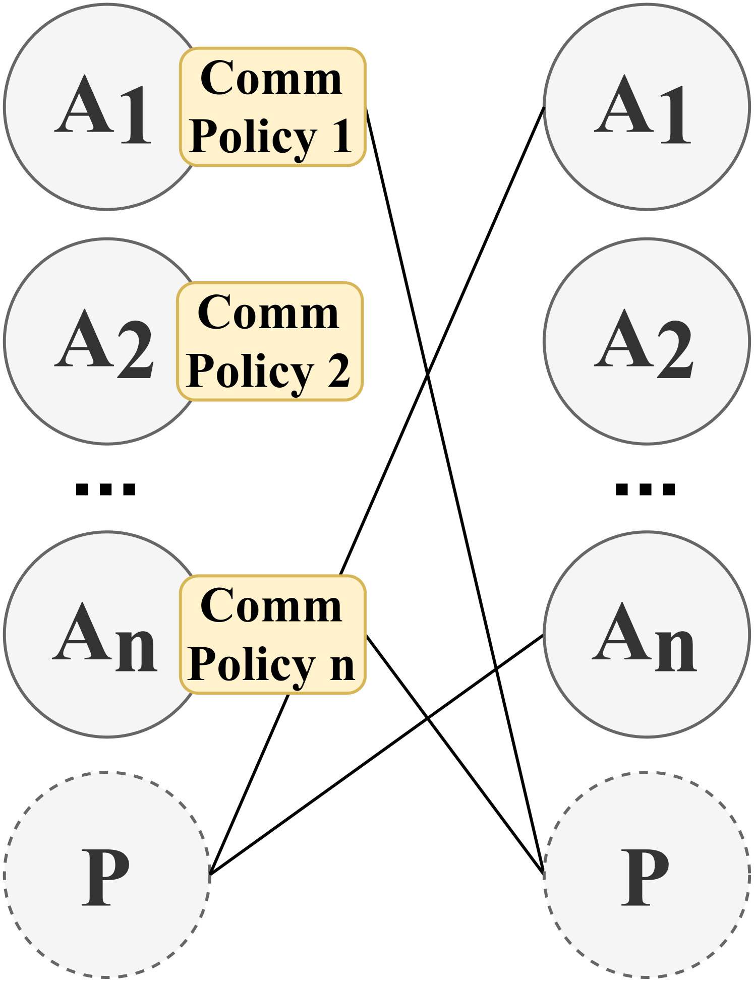
The image depicts a diagram illustrating communication policies between entities labeled A1, A2, ..., An, and P. The diagram shows connections between these entities, indicating communication pathways or relationships.
### Components/Axes
* **Nodes (Left Side):**
* A1: Represented by a circle with a solid gray outline.
* A2: Represented by a circle with a solid gray outline.
* ... (Ellipsis): Indicates a continuation of the pattern.
* An: Represented by a circle with a solid gray outline.
* P: Represented by a circle with a dashed gray outline.
* **Nodes (Right Side):**
* A1: Represented by a circle with a solid gray outline.
* A2: Represented by a circle with a solid gray outline.
* ... (Ellipsis): Indicates a continuation of the pattern.
* An: Represented by a circle with a solid gray outline.
* P: Represented by a circle with a dashed gray outline.
* **Communication Policies:**
* Comm Policy 1: A rounded rectangle with a light yellow fill and a darker yellow border, positioned next to A1 on the left side.
* Comm Policy 2: A rounded rectangle with a light yellow fill and a darker yellow border, positioned next to A2 on the left side.
* Comm Policy n: A rounded rectangle with a light yellow fill and a darker yellow border, positioned next to An on the left side.
* **Connections:** Solid black lines indicate communication pathways between the left and right sides.
### Detailed Analysis
* **Node Placement:** The nodes A1, A2, ..., An, and P are arranged vertically on both the left and right sides of the diagram.
* **Communication Policy Placement:** Each communication policy (Comm Policy 1, Comm Policy 2, ..., Comm Policy n) is placed adjacent to the corresponding 'A' node on the left side.
* **Connections:**
* 'Comm Policy 1' (associated with A1 on the left) connects to 'An' and 'P' on the right.
* 'Comm Policy n' (associated with An on the left) connects to 'A1' on the right.
### Key Observations
* The diagram illustrates a network where communication policies associated with entities A1 through An on one side dictate connections to entities on the other side.
* The 'P' node is represented with a dashed outline, potentially indicating a different type of entity or a different state.
* The ellipsis (...) suggests that there may be multiple 'A' entities and corresponding communication policies.
### Interpretation
The diagram represents a communication network where policies govern interactions between entities. The 'A' entities (A1, A2, ..., An) each have an associated communication policy that determines which entities on the other side they can communicate with. The 'P' entity appears to be a distinct element in this network, possibly representing a central point or a different type of participant. The connections show that communication is not necessarily one-to-one; for example, A1's policy allows it to communicate with both An and P on the other side. The dashed outline of 'P' might indicate that it is a potential or optional participant in the communication network.