## Diagram: Partitioned Grid with Modular Arithmetic and Transformations
### Overview
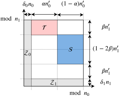
The image depicts a partitioned grid divided into regions labeled with mathematical expressions and parameters. The grid is structured with horizontal and vertical axes labeled "mod n₁" and "mod n₀," respectively. Arrows indicate directional transformations with associated parameters (e.g., α, β, δ), and regions are color-coded (pink, blue, gray) to denote distinct zones.
### Components/Axes
- **Axes**:
- Horizontal axis: "mod n₀" (rightward direction).
- Vertical axis: "mod n₁" (upward direction).
- **Regions**:
- **Top-left**: Pink region labeled **T**.
- **Bottom-right**: Blue region labeled **S**.
- **Bottom-left**: Gray region labeled **Z₁**.
- **Left column**: Gray region labeled **Z₀** (spanning the full height of the grid).
- **Parameters**:
- **Top edge**:
- Left: **δ₀n₀** (leftward arrow).
- Center: **αn₀** (rightward arrow).
- Right: **(1 - α)n₀** (rightward arrow).
- **Right edge**:
- Top: **βn₁** (upward arrow).
- Bottom: **βn₁** (downward arrow).
- **Bottom edge**:
- Right: **δ₁n₁** (leftward arrow).
- **Left edge**:
- Top: **βn₁** (downward arrow).
- Bottom: **βn₁** (upward arrow).
### Detailed Analysis
- **Grid Structure**:
- The grid is divided into four quadrants by dashed lines.
- **Z₀** occupies the entire left column, while **Z₁** spans the bottom row.
- **T** (pink) and **S** (blue) are confined to the top-left and bottom-right quadrants, respectively.
- **Directional Transformations**:
- **Horizontal transformations**:
- From **mod n₀** to **mod n₁**:
- **αn₀** and **(1 - α)n₀** suggest partitioning of **n₀** into two components.
- **δ₀n₀** indicates a residual or offset term.
- **Vertical transformations**:
- **βn₁** appears on both sides of the grid, suggesting symmetry or bidirectional flow.
- **δ₁n₁** on the bottom edge implies a residual term in the vertical direction.
- **Color Coding**:
- **Pink (T)**: Likely represents a transformed or active zone.
- **Blue (S)**: May denote a stable or target region.
- **Gray (Z₀, Z₁)**: Neutral or foundational zones.
### Key Observations
1. **Modular Arithmetic**: The labels "mod n₀" and "mod n₁" imply operations within modular arithmetic frameworks.
2. **Parameter Relationships**:
- **α** and **β** are fractions (e.g., **αn₀**, **βn₁**), suggesting proportional scaling.
- **δ₀n₀** and **δ₁n₁** represent deviations or residuals from the primary terms.
3. **Symmetry**: The repeated use of **βn₁** on opposite edges hints at balanced transformations.
### Interpretation
This diagram likely represents a mathematical or computational process involving modular partitioning and directional transformations. The regions **T** and **S** could symbolize distinct states or phases, with **Z₀** and **Z₁** acting as transitional or boundary zones. The parameters **α**, **β**, and **δ** govern the scaling and offset of these transformations, potentially modeling interactions between modular systems. The symmetry in **βn₁** suggests a balanced or reversible process, while residuals (**δ₀n₀**, **δ₁n₁**) account for deviations from idealized transformations.
The structure aligns with concepts in number theory, cryptography, or signal processing, where modular arithmetic and partitioning are foundational. The absence of numerical values implies a generalized framework applicable to various systems.