## Scatter Plot: Perceived Angle Delta vs. Intended Angle
### Overview
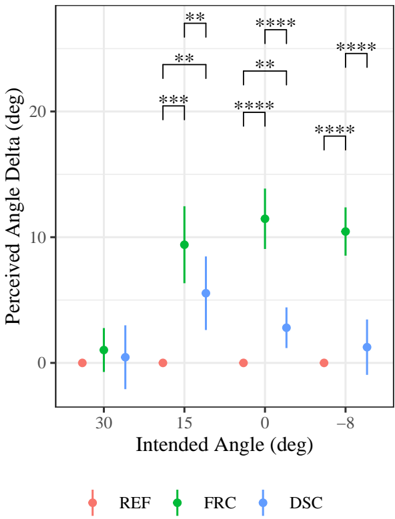
The image is a scatter plot showing the relationship between "Intended Angle" (in degrees) and "Perceived Angle Delta" (in degrees) for three different conditions: REF (reference), FRC, and DSC. Error bars are displayed for each data point, indicating variability. Statistical significance is indicated by asterisks above the data points.
### Components/Axes
* **X-axis:** Intended Angle (deg), with values at 30, 15, 0, and -8 degrees.
* **Y-axis:** Perceived Angle Delta (deg), ranging from 0 to 20.
* **Legend:** Located at the bottom of the chart.
* REF: Red data points and line.
* FRC: Green data points and line.
* DSC: Blue data points and line.
* **Statistical Significance:** Asterisks above the data points indicate statistical significance levels:
* \*\* : p < 0.01
* \*\*\* : p < 0.001
* \*\*\*\* : p < 0.0001
### Detailed Analysis
**REF (Red):**
* Trend: The Perceived Angle Delta remains approximately constant at 0 degrees across all Intended Angles.
* Data Points:
* Intended Angle 30 deg: Perceived Angle Delta ~ 0 deg
* Intended Angle 15 deg: Perceived Angle Delta ~ 0 deg
* Intended Angle 0 deg: Perceived Angle Delta ~ 0 deg
* Intended Angle -8 deg: Perceived Angle Delta ~ 0 deg
**FRC (Green):**
* Trend: The Perceived Angle Delta increases from 30 to 15 degrees, then remains relatively constant from 15 to -8 degrees.
* Data Points:
* Intended Angle 30 deg: Perceived Angle Delta ~ 2 deg
* Intended Angle 15 deg: Perceived Angle Delta ~ 9 deg
* Intended Angle 0 deg: Perceived Angle Delta ~ 12 deg
* Intended Angle -8 deg: Perceived Angle Delta ~ 10 deg
**DSC (Blue):**
* Trend: The Perceived Angle Delta increases from 30 to 0 degrees, then decreases slightly from 0 to -8 degrees.
* Data Points:
* Intended Angle 30 deg: Perceived Angle Delta ~ 2 deg
* Intended Angle 15 deg: Perceived Angle Delta ~ 6 deg
* Intended Angle 0 deg: Perceived Angle Delta ~ 3 deg
* Intended Angle -8 deg: Perceived Angle Delta ~ 2 deg
**Statistical Significance:**
* FRC vs. REF:
* Intended Angle 30 deg: \*\*
* Intended Angle 15 deg: \*\*\*
* Intended Angle 0 deg: \*\*\*\*
* Intended Angle -8 deg: \*\*\*\*
* DSC vs. REF:
* Intended Angle 30 deg: \*\*
* Intended Angle 15 deg: \*\*
* Intended Angle 0 deg: \*\*\*\*
* Intended Angle -8 deg: \*\*\*\*
* FRC vs. DSC:
* Intended Angle 30 deg: N/A
* Intended Angle 15 deg: \*\*
* Intended Angle 0 deg: \*\*\*\*
* Intended Angle -8 deg: \*\*\*
### Key Observations
* The REF condition consistently shows a Perceived Angle Delta of approximately 0 degrees, regardless of the Intended Angle.
* The FRC condition exhibits a higher Perceived Angle Delta compared to REF, especially at Intended Angles of 15, 0, and -8 degrees.
* The DSC condition shows a Perceived Angle Delta that is generally higher than REF, but lower than FRC, except at 30 degrees.
* The statistical significance tests indicate that the differences between FRC/DSC and REF are highly significant (p < 0.0001) at Intended Angles of 0 and -8 degrees.
### Interpretation
The data suggests that the FRC and DSC conditions introduce a systematic bias in the perception of angles, leading to a larger difference between the intended and perceived angles compared to the REF condition. The FRC condition appears to have a stronger effect on angle perception than the DSC condition. The statistical significance tests confirm that these differences are not due to random chance. The asterisks indicate the p-values for the statistical significance of the difference between the conditions. For example, the four asterisks above the FRC data point at 0 degrees indicate a p-value of less than 0.0001, meaning that the difference between FRC and REF at this angle is highly statistically significant.