## State Diagram: Process Workflow with Human-In-The-Loop (HITL) Intervention
### Overview
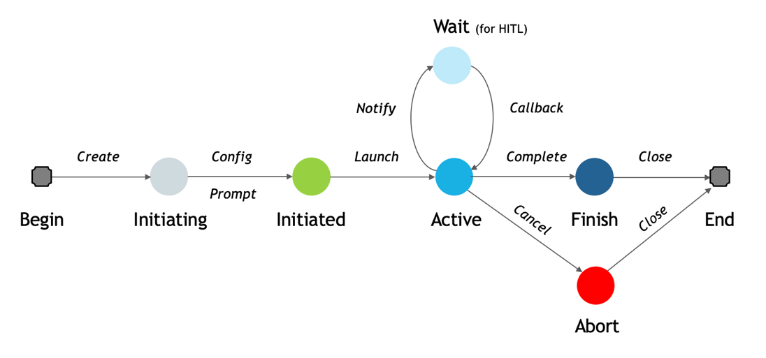
The image displays a state transition diagram (or workflow) illustrating the lifecycle of a process. The flow moves generally from left to right, starting at "Begin" and ending at "End," with a central "Active" state that can loop to a "Wait" state for human intervention and can also branch to an "Abort" state. The diagram uses colored circles to represent states and labeled arrows to represent transitions or actions.
### Components/States
The diagram consists of eight distinct states, represented by circles or rounded squares, arranged in a specific spatial layout:
1. **Begin** (Far left): A gray rounded square. This is the entry point.
2. **Initiating** (Left of center): A light gray circle.
3. **Initiated** (Center-left): A green circle.
4. **Active** (Center): A cyan (bright blue) circle. This is a central hub state.
5. **Wait (for HITL)** (Above "Active"): A light blue circle. The label includes "(for HITL)" in parentheses, indicating "Human-In-The-Loop."
6. **Finish** (Center-right): A dark blue circle.
7. **Abort** (Below "Finish"): A red circle.
8. **End** (Far right): A gray rounded square. This is the terminal point.
### Detailed Analysis: Transitions and Flow
The states are connected by directional arrows, each labeled with an action or event that triggers the transition. The flow is as follows:
* **From "Begin" to "Initiating":** Transition labeled *Create*.
* **From "Initiating" to "Initiated":** Two parallel transitions are shown:
* An arrow labeled *Config*.
* An arrow labeled *Prompt*.
* **From "Initiated" to "Active":** Transition labeled *Launch*.
* **From "Active" to "Wait (for HITL)":** Transition labeled *Notify*.
* **From "Wait (for HITL)" back to "Active":** Transition labeled *Callback*. This creates a loop between the "Active" and "Wait" states.
* **From "Active" to "Finish":** Transition labeled *Complete*.
* **From "Active" to "Abort":** Transition labeled *Cancel*.
* **From "Finish" to "End":** Transition labeled *Close*.
* **From "Abort" to "End":** Transition labeled *Close*.
### Key Observations
1. **Central Hub:** The "Active" state is the most connected node, with four outgoing transitions (*Notify*, *Complete*, *Cancel*) and one incoming from the loop (*Callback*).
2. **Human-In-The-Loop Loop:** The "Wait (for HITL)" state forms a dedicated loop with "Active," indicating a process that can pause for human input and then resume.
3. **Two Terminal Paths:** The process can conclude via two distinct paths to the "End" state: a successful path through "Finish" or a failure/termination path through "Abort." Both final transitions are labeled *Close*.
4. **Color Semantics:** Colors appear to signify state type:
* **Gray (Begin/End):** Terminal/Bookend states.
* **Green (Initiated):** A "ready" or "prepared" state.
* **Cyan (Active):** The primary operational state.
* **Light Blue (Wait):** A passive, waiting state.
* **Dark Blue (Finish):** A successful completion state.
* **Red (Abort):** A critical failure or cancellation state.
5. **Parallel Initialization:** The "Initiating" to "Initiated" step has two labels (*Config*, *Prompt*), suggesting these actions may happen concurrently or are both required to advance the state.
### Interpretation
This diagram models a robust, interruptible process workflow. It is not a simple linear sequence but a state machine that accounts for real-world complexities.
* **Process Resilience:** The inclusion of a "Wait (for HITL)" loop demonstrates a design for processes requiring human oversight, approval, or input, making the system collaborative rather than fully autonomous.
* **Error Handling:** The explicit "Abort" state, reachable from "Active" via a *Cancel* action, provides a clear pathway for graceful termination upon failure or user intervention, separate from successful completion.
* **Lifecycle Clarity:** The flow clearly demarcates phases: initialization (*Create, Config, Prompt*), execution (*Launch, Active*), potential interruption (*Notify, Callback*), and conclusion (*Complete/Cancel -> Finish/Abort -> Close -> End*).
* **Ambiguity in "Close":** The use of the same label *Close* for transitions from both "Finish" and "Abort" to "End" is notable. It suggests that the final cleanup or resource release action is identical regardless of whether the process succeeded or was aborted, which is a sensible design for resource management.
**In essence, this diagram depicts a managed process that can be configured, launched, actively run with the option for human pause/resume, and then formally concluded through either success or cancellation.**