TECHNICAL ASSET FINGERPRINT
c4972f9799639b5546f9362f
Click to view fullscreen
Press ESC or click to close
FOUND IN PAPERS
EXPERT: healer-alpha-free VERSION 1
RUNTIME: free/openrouter/healer-alpha
INTEL_VERIFIED
\n
## Diagram: Iterative Code Generation and Refinement Process
### Overview
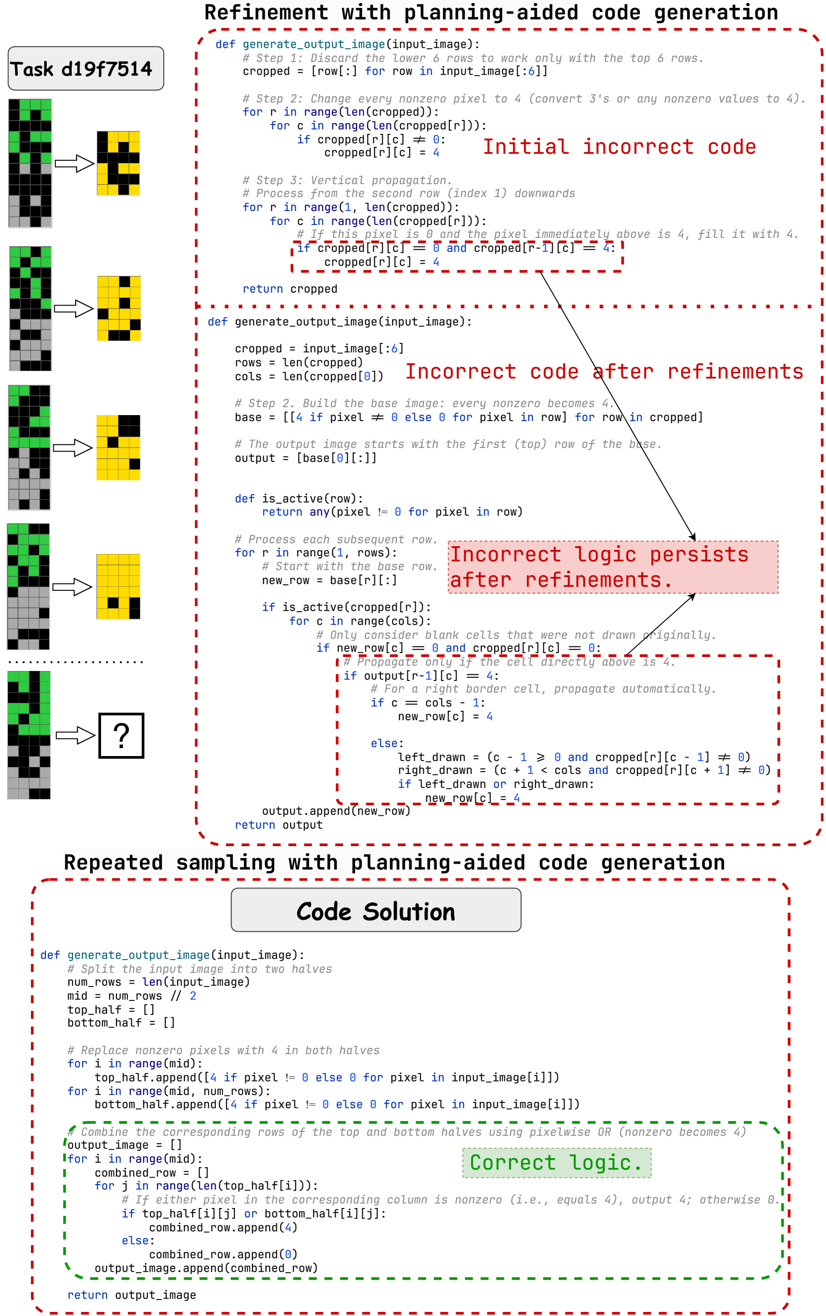
The image is a technical diagram illustrating an iterative process of generating and refining code to solve a specific image transformation task (labeled "Task d19f7514"). It contrasts incorrect approaches with a final correct solution, highlighting the evolution of logic through two main phases: "Refinement with planning-aided code generation" and "Repeated sampling with planning-aided code generation." The diagram includes visual examples of the task, multiple Python code blocks with annotations, and explanatory labels.
### Components and Layout
The diagram is organized into three primary vertical sections:
1. **Left Column (Visual Task Examples):**
* A series of five pixel grid examples, each showing an input grid (left) and an output grid (right) connected by an arrow.
* The grids are 6 rows tall. Input grids contain black, grey, and green pixels. Output grids contain black and yellow pixels.
* The first four examples show completed transformations. The fifth example has a question mark (`?`) in the output box, indicating the unsolved problem the code aims to address.
* A label at the top reads: `Task d19f7514`.
2. **Top-Right Section (Refinement Phase):**
* **Title:** `Refinement with planning-aided code generation` (in bold, black text).
* This section contains two Python code blocks, each enclosed in a red dashed box.
* **First Code Block:** Labeled with red text: `Initial incorrect code`. It defines a function `generate_output_image(input_image)` with three steps: cropping, pixel value replacement, and vertical propagation.
* **Second Code Block:** Labeled with red text: `Incorrect code after refinements`. It shows a more structured but still flawed version of the function. A red annotation box points to a specific logic section with the text: `Incorrect logic persists after refinements.`
3. **Bottom-Right Section (Repeated Sampling Phase):**
* **Title:** `Repeated sampling with planning-aided code generation` (in bold, black text).
* A central label reads: `Code Solution`.
* A single, larger Python code block is enclosed in a red dashed box. A green dashed box highlights a specific section of this code, accompanied by a green annotation: `Correct logic.`
### Detailed Analysis: Code Transcription and Logic
#### 1. Initial Incorrect Code (Top Block)
```python
def generate_output_image(input_image):
# Step 1: Discard the lower 6 rows to work only with the top 6 rows.
cropped = [row[:] for row in input_image[:6]]
# Step 2: Change every nonzero pixel to 4 (convert 3's or any nonzero values to 4).
for r in range(len(cropped)):
for c in range(len(cropped[r])):
if cropped[r][c] != 0:
cropped[r][c] = 4
# Step 3: Vertical propagation.
# Process from the second row (index 1) downwards
for r in range(1, len(cropped)):
for c in range(len(cropped[r])):
# If this pixel is 0 and the pixel immediately above is 4, fill it with 4.
if cropped[r][c] == 0 and cropped[r-1][c] == 4:
cropped[r][c] = 4
return cropped
```
* **Logic:** Crops the input to the first 6 rows, replaces all non-zero pixels with the value 4, then performs a simple vertical fill: any zero pixel directly below a 4 becomes a 4.
#### 2. Incorrect Code After Refinements (Middle Block)
```python
def generate_output_image(input_image):
cropped = input_image[:6]
rows = len(cropped)
cols = len(cropped[0])
# Step 2. Build the base image: every nonzero becomes 4.
base = [[4 if pixel != 0 else 0 for pixel in row] for row in cropped]
# The output image starts with the first (top) row of the base.
output = [base[0][:]]
def is_active(row):
return any(pixel != 0 for pixel in row)
# Process each subsequent row.
for r in range(1, rows):
# Start with the base row.
new_row = base[r][:]
if is_active(cropped[r]):
for c in range(cols):
# Only consider blank cells that were not drawn originally.
if new_row[c] == 0 and cropped[r][c] == 0:
# Propagate only if the cell directly above is 4.
if output[r-1][c] == 4:
# For a right border cell, propagate automatically.
if c == cols - 1:
new_row[c] = 4
else:
left_drawn = (c - 1 >= 0 and cropped[r][c - 1] != 0)
right_drawn = (c + 1 < cols and cropped[r][c + 1] != 0)
if left_drawn or right_drawn:
new_row[c] = 4
output.append(new_row)
return output
```
* **Logic:** This version introduces more complex conditions. It creates a `base` grid (non-zero -> 4). It then builds the `output` row by row. For each row, if the original input row was "active" (had any non-zero pixel), it attempts to fill zeros in the `new_row` based on: 1) the pixel above in the `output` being 4, and 2) additional border or neighbor-drawn conditions. The annotation indicates this logic is still flawed.
#### 3. Correct Code Solution (Bottom Block)
```python
def generate_output_image(input_image):
# Split the input image into two halves
num_rows = len(input_image)
mid = num_rows // 2
top_half = []
bottom_half = []
# Replace nonzero pixels with 4 in both halves
for i in range(mid):
top_half.append([4 if pixel != 0 else 0 for pixel in input_image[i]])
for i in range(mid, num_rows):
bottom_half.append([4 if pixel != 0 else 0 for pixel in input_image[i]])
# Combine the corresponding rows of the top and bottom halves using pixelwise OR (nonzero becomes 4)
output_image = []
for i in range(mid):
combined_row = []
for j in range(len(top_half[i])):
# If either pixel in the corresponding column is nonzero (i.e., equals 4), output 4; otherwise 0.
if top_half[i][j] or bottom_half[i][j]:
combined_row.append(4)
else:
combined_row.append(0)
output_image.append(combined_row)
return output_image
```
* **Logic (Correct):** This solution takes a fundamentally different approach. It splits the input image into top and bottom halves. It processes each half independently, converting non-zero pixels to 4. It then creates the output by combining corresponding rows from the two halves using a pixel-wise logical OR operation. If a pixel is 4 (non-zero) in *either* the top-half row or the bottom-half row at the same column, the output pixel is 4.
### Key Observations
1. **Task Pattern:** The visual examples suggest the transformation rule: The output is a 6-row grid where a pixel is yellow (value 4) if the corresponding pixel in the *top half* (first 3 rows) OR the *bottom half* (last 3 rows) of the input is non-zero. The incorrect codes tried to model this as a vertical propagation or neighbor-based fill, which is more complex and error-prone.
2. **Evolution of Approach:** The process moves from a simple, incorrect vertical fill model to a more complex conditional model, and finally to a correct, simpler model based on splitting and combining halves.
3. **Annotation Strategy:** Red is used consistently to highlight incorrect code and logic. Green is used to highlight the correct logic, creating a clear visual distinction between failure and success.
4. **Spatial Grounding:** The incorrect logic annotations are placed directly adjacent to the specific code lines they describe. The "Correct logic" label is placed within the green dashed box that surrounds the core combining loop of the final solution.
### Interpretation
This diagram serves as a case study in iterative problem-solving for algorithmic tasks. It demonstrates that:
* **Initial Intuition Can Be Misleading:** The first attempts modeled the transformation as a local propagation effect (like a flood fill), which aligns with how one might visually trace patterns but does not match the actual global rule.
* **Refinement Without Re-evaluation is Insufficient:** The second code block added complexity (border checks, neighbor checks) but was built upon the same flawed foundational assumption, so the core error persisted.
* **Correct Solution Requires Re-framing the Problem:** The breakthrough came from abandoning the propagation model and re-framing the task as a simple composition of two independent sub-images (top and bottom halves). This "planning-aided" shift in perspective led to a correct and more elegant solution.
* **The Value of Visual Examples:** The pixel grid examples on the left are crucial. They provide the ground truth that the code must match. The final unsolved example (`?`) represents the test case that likely prompted the re-evaluation and eventual correct solution.
The diagram effectively communicates that successful code generation for visual tasks often depends less on intricate conditional logic and more on correctly identifying the underlying compositional structure of the transformation.
DECODING INTELLIGENCE...