## Diagram: Graph Reduction Steps
### Overview
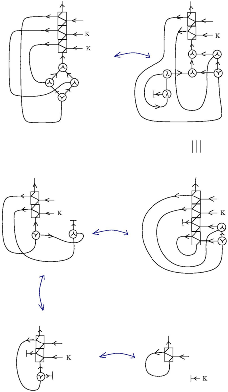
The image depicts a series of graph transformations, likely representing a reduction or simplification process. The diagrams show directed graphs being modified through a sequence of steps, indicated by curved arrows. The graphs consist of nodes and edges, with specific node types labeled with symbols like "K" and "Y".
### Components/Axes
* **Nodes:** Represented by circles and rectangles. Some nodes are labeled with "K", "Y", or "λ".
* **Edges:** Represented by lines with arrowheads, indicating direction.
* **Transformation Arrows:** Curved arrows in blue indicate the transformation steps between the graphs.
* **Equivalence Symbol:** "|||" indicates equivalence between two graph states.
### Detailed Analysis
The diagram consists of six sub-diagrams arranged in a 2x3 grid. Each sub-diagram represents a state in the graph transformation process.
1. **Top-Left Diagram:**
* A vertical stack of four rectangular nodes. Each node has an incoming edge from the left, labeled "K" on the right side of the node.
* The bottom node of the stack has an outgoing edge that connects to a cluster of four circular nodes labeled "Y".
* The "Y" nodes are interconnected with edges forming a diamond shape.
* Edges connect the "Y" nodes back to the vertical stack.
2. **Top-Right Diagram:**
* Transformation from the top-left diagram is indicated by a blue curved arrow.
* Similar vertical stack of four rectangular nodes with incoming edges labeled "K".
* A cluster of three circular nodes labeled "Y".
* Two circular nodes labeled "λ".
* Edges connect these nodes in a more complex configuration compared to the top-left diagram.
3. **Middle-Center Diagram:**
* "|||" symbol indicating equivalence between the top-right and middle-left diagrams.
4. **Middle-Left Diagram:**
* Similar vertical stack of four rectangular nodes with incoming edges labeled "K".
* Two circular nodes labeled "Y".
* Edges connect these nodes in a simpler configuration compared to the top diagrams.
5. **Middle-Right Diagram:**
* Transformation from the middle-left diagram is indicated by a blue curved arrow.
* Similar vertical stack of four rectangular nodes with incoming edges labeled "K".
* Two circular nodes labeled "Y".
* Edges connect these nodes in a more complex configuration compared to the middle-left diagram.
6. **Bottom-Left Diagram:**
* Transformation from the middle-right diagram is indicated by a blue curved arrow.
* A vertical stack of one rectangular node with incoming edges labeled "K".
* One circular node labeled "Y".
* Edges connect these nodes in a simpler configuration compared to the middle diagrams.
7. **Bottom-Right Diagram:**
* Transformation from the bottom-left diagram is indicated by a blue curved arrow.
* A vertical stack of one rectangular node with incoming edges labeled "K".
* One circular node labeled "Y".
* Edges connect these nodes in a simpler configuration compared to the bottom-left diagram.
### Key Observations
* The number of rectangular nodes in the vertical stack decreases from four to one throughout the transformation process.
* The complexity of the connections between the circular nodes varies across the diagrams.
* The "K" labels remain consistent throughout the transformation.
* The "Y" and "λ" labels appear on circular nodes, suggesting different node types.
### Interpretation
The diagram illustrates a step-by-step reduction of a graph structure. The transformations appear to simplify the graph by reducing the number of nodes and edges while preserving certain key elements (e.g., "K" labels). The equivalence symbol "|||" suggests that the transformations maintain some form of functional equivalence despite the structural changes. The presence of "Y" and "λ" nodes indicates that the graph may represent a system with different types of components or operations. The overall process seems to be a simplification or optimization of the initial graph structure.