\n
## Diagram: Pneumatic Circuit Schematic
### Overview
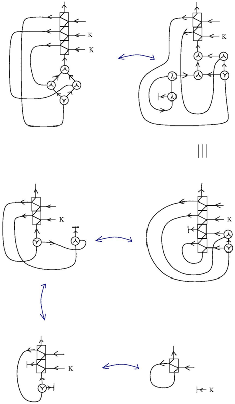
The image depicts a series of pneumatic circuit schematics, illustrating a sequential operation involving directional control valves, cylinders, and potentially pressure regulation. The schematics are arranged in a flow-like manner, suggesting a step-by-step process. Each schematic shows a different stage of the circuit's operation, with arrows indicating the flow of air and the sequence of events.
### Components/Axes
The diagram utilizes standard pneumatic symbols. Key components include:
* **Directional Control Valves:** Represented by square symbols with arrows indicating flow paths. These valves are marked with "K" on the input/output lines. The valves have multiple ports, indicated by the number of arrows.
* **Cylinders (Double-Acting):** Represented by rectangles with double-headed arrows indicating piston movement.
* **Pilot Valves/Control Lines:** Represented by small circles with "Y" inside, connected to the directional control valves.
* **Flow Lines:** Represented by solid lines with arrowheads indicating the direction of airflow.
* **Connecting Arrows:** Curved arrows indicating the sequence of operation between the different stages.
* **Lambda (λ) Symbol:** Appears within a circular element in one of the schematics. Its function is unclear without additional context.
* **Triple Vertical Lines (|||):** Separates two stages of the circuit.
### Detailed Analysis or Content Details
The diagram consists of five distinct stages, arranged in a roughly clockwise manner.
**Stage 1 (Top-Left):**
* A directional control valve with multiple ports (approximately 5 ports) is shown.
* Input/output lines are labeled "K".
* Two cylinders are connected to the valve, each with a pilot valve ("Y") controlling its operation.
* Air flows into the valve from the top and exits to the cylinders.
**Stage 2 (Top-Right):**
* A directional control valve with multiple ports (approximately 5 ports) is shown.
* Input/output lines are labeled "K".
* Two cylinders are connected to the valve, each with a pilot valve ("Y") controlling its operation.
* A circular element containing the lambda (λ) symbol is connected to the valve.
* An arrow connects this stage to Stage 1, indicating a return or feedback loop.
**Stage 3 (Center-Left):**
* A directional control valve with multiple ports (approximately 5 ports) is shown.
* Input/output lines are labeled "K".
* Two cylinders are connected to the valve, each with a pilot valve ("Y") controlling its operation.
* An arrow connects this stage to Stage 4, indicating a sequential flow.
**Stage 4 (Center-Right):**
* A directional control valve with multiple ports (approximately 5 ports) is shown.
* Input/output lines are labeled "K".
* Two cylinders are connected to the valve, each with a pilot valve ("Y") controlling its operation.
* An arrow connects this stage to Stage 3, indicating a sequential flow.
**Stage 5 (Bottom-Center):**
* A directional control valve with fewer ports (approximately 3 ports) is shown.
* Input/output lines are labeled "K".
* A single cylinder is connected to the valve, with a pilot valve ("Y") controlling its operation.
* An arrow connects this stage to Stage 1, completing the sequence.
### Key Observations
* The "K" label consistently appears on the input/output lines of the directional control valves, suggesting it represents a common pressure source or control signal.
* The pilot valves ("Y") are crucial for controlling the operation of the cylinders.
* The sequence of stages suggests a cyclical operation, with the final stage returning to the initial stage.
* The lambda (λ) symbol in Stage 2 is an anomaly and its function is unclear.
* The number of ports on the directional control valves varies, indicating different levels of control and complexity.
### Interpretation
The diagram illustrates a pneumatic circuit designed for a sequential operation, likely involving the coordinated movement of multiple cylinders. The valves control the flow of air to the cylinders, and the pilot valves provide a means of controlling the valves themselves. The cyclical nature of the sequence suggests an automated process, potentially involving repetitive tasks. The "K" label likely represents a compressed air supply or a control signal that initiates the sequence. The lambda symbol could represent a sensor or a specific control function within the circuit, but its exact purpose is unknown without further information. The diagram is a high-level representation of the circuit, and further details would be needed to understand the specific timing and control logic. The diagram is a functional block diagram, and does not provide specific dimensions or performance characteristics.