## Directed Graph: Process Flow and Entity Relationships
### Overview
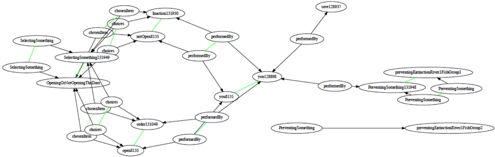
The image displays a directed node-link diagram representing a complex decision-making process or simulation logic. The graph maps various states, actions, and entities (represented as ellipses) connected by directed edges (arrows). The flow appears to originate from decision-making nodes on the left, passing through actor nodes in the center, and terminating in outcome-based nodes on the right. Green edges appear to highlight specific, active, or chosen paths within the logic flow.
### Components/Axes
* **Nodes (Ellipses):** Contain text labels identifying specific states, actions, or entities.
* **Edges (Arrows):**
* **Black Arrows:** Represent standard relationships or transitions.
* **Green Arrows:** Represent highlighted or selected relationships (e.g., "chosenItem" or specific active transitions).
* **Labels on Edges:**
* `chosenItem`: Indicates a selection made from a set of options.
* `choices`: Indicates a branching point or set of available options.
* `performedBy`: Indicates the agent or entity responsible for an action.
### Detailed Analysis
#### 1. Left Cluster (Decision/Action Logic)
* **Nodes:**
* `SelectingSomething` (Top-left)
* `SelectingSomething` (Middle-left)
* `SelectingSomething131949` (Center-left)
* `OpeningOrNotOpeningTheDam` (Center-left, below 131949)
* **Flow:** The two `SelectingSomething` nodes point toward `SelectingSomething131949`. From `SelectingSomething131949`, the flow branches out to `Inaction131950`, `notOpen8135`, `OpeningOrNotOpeningTheDam`, `order131049`, and `open8135`.
* **Green Highlights:** A green line connects `SelectingSomething` (top-left) to `SelectingSomething131949`, and another connects `SelectingSomething131949` to `OpeningOrNotOpeningTheDam`.
#### 2. Central Cluster (Execution/Agents)
* **Nodes:**
* `Inaction131950` (Top-center)
* `notOpen8135` (Top-center)
* `order131049` (Bottom-center)
* `open8135` (Bottom-center)
* `you8131` (Center)
* `you128898` (Center-right)
* **Flow:** The states `Inaction131950`, `notOpen8135`, `order131049`, and `open8135` are connected to the agent nodes `you8131` and `you128898` via `performedBy` edges.
* **Green Highlights:** A green line connects `Inaction131950` to `you128898`, and `you8131` to `you128898`. A green line also connects `order131049` to `open8135`.
#### 3. Right Cluster (Outcomes/Prevention)
* **Nodes:**
* `save128937` (Top-right)
* `PreventingSomething` (Middle-right, top)
* `PreventingSomething131948` (Middle-right)
* `PreventingSomething` (Middle-right, bottom)
* `preventingExtinctionRiver1FishGroup1` (Middle-right, far right)
* `preventingExtinctionRiver1FishGroup2` (Bottom-right)
* **Flow:** `you128898` acts as a hub, connecting to `save128937` and `PreventingSomething131948`. The `PreventingSomething` nodes form a sub-cluster related to `preventingExtinctionRiver1FishGroup1`.
* **Green Highlights:** A green line connects `PreventingSomething131948` to `preventingExtinctionRiver1FishGroup1`.
### Key Observations
* **Hub-and-Spoke Structure:** The nodes `you8131` and `you128898` act as central processing hubs, aggregating actions from the left side and directing them toward outcomes on the right.
* **Decision Branching:** The node `OpeningOrNotOpeningTheDam` is a critical junction, with multiple `choices` and `chosenItem` edges radiating from it, suggesting it is a primary decision point in the logic.
* **Green Pathing:** The green lines appear to trace a specific "successful" or "active" path through the logic, specifically highlighting the transition from `SelectingSomething` -> `OpeningOrNotOpeningTheDam` -> `open8135` -> `you8131` -> `you128898` -> `PreventingSomething131948` -> `preventingExtinctionRiver1FishGroup1`.
### Interpretation
This diagram appears to be a trace of a software agent or a simulation model, likely related to environmental management (given the "Dam" and "preventingExtinction" labels).
* **Logic Flow:** The system evaluates a decision (`SelectingSomething`), executes an action (`OpeningOrNotOpeningTheDam`), and assigns that action to an agent (`you...`).
* **Agent-Based Modeling:** The presence of `you8131` and `you128898` suggests an agent-based model where specific entities perform actions that lead to environmental outcomes.
* **Simulation Trace:** The green lines likely represent the *actual* path taken during a specific simulation run, distinguishing it from the potential paths (black lines) that were available but not taken. The graph demonstrates a causal chain: Decision -> Action -> Agent Execution -> Outcome.