TECHNICAL ASSET FINGERPRINT
c6533350f07f77e65837ca86
Click to view fullscreen
Press ESC or click to close
FOUND IN PAPERS
EXPERT: gemini-2.5-flash-free VERSION 1
RUNTIME: google-free/gemini-2.5-flash
INTEL_VERIFIED
## Diagram: Hardware Implementations of Probabilistic Bits and Hybrid Computer Architecture
### Overview
This technical diagram illustrates two main concepts:
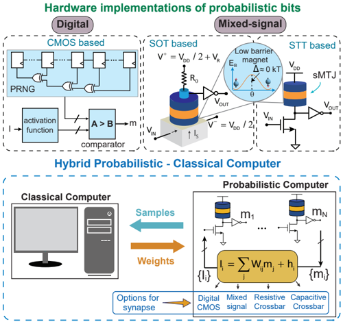
1. **Hardware implementations of probabilistic bits**: This top section details different circuit designs for generating probabilistic bits, categorized into "Digital" (CMOS based) and "Mixed-signal" (SOT based and STT based) approaches.
2. **Hybrid Probabilistic - Classical Computer**: This bottom section presents a high-level architecture for a hybrid computing system that integrates a classical computer with a probabilistic computer, showing their interaction and potential synapse technologies.
### Section 1: Hardware Implementations of Probabilistic Bits
#### Overview of Section 1
This section, located in the upper half of the image, presents three distinct hardware architectures designed to implement probabilistic bits. It is divided into two main categories: "Digital" and "Mixed-signal".
#### Digital Implementations
Located in the top-left quadrant, under the "Digital" label.
##### CMOS based
This sub-section depicts a CMOS-based circuit for generating probabilistic bits.
* **Components**:
* **PRNG (Pseudo-Random Number Generator)**: Shown as a series of four D-type flip-flops connected in a feedback loop with two XOR gates. The output of the PRNG feeds into a comparator.
* **Activation function**: A block labeled "activation function" takes an input "I".
* **Comparator**: A block labeled "A > B" (comparator) has two inputs, A and B, and produces an output "m".
* **Flow**: An input signal "I" enters the "activation function" block. The output of the "activation function" feeds into the 'A' input of the "comparator". The output of the "PRNG" feeds into the 'B' input of the "comparator". The "comparator" then outputs "m", which represents the probabilistic bit.
#### Mixed-signal Implementations
Located in the top-right quadrant, under the "Mixed-signal" label. This category is further divided into "SOT based" and "STT based" approaches.
##### SOT based
This sub-section, positioned in the middle-right, illustrates a Spin-Orbit Torque (SOT) based probabilistic bit implementation.
* **Components**:
* A device resembling a Magnetic Tunnel Junction (MTJ) is shown, connected to a resistor `R_0` at its top.
* An inverter gate is connected to the output of the `R_0` and MTJ combination, producing `V_OUT`.
* A current source `I_s` is shown injecting current into the base of the MTJ device.
* Voltage inputs `V_IN` and `V_OUT` are indicated.
* Two reference voltages are defined: `V^+ = V_DD / 2 + V_R` and `V^- = V_DD / 2`.
* **Inset Diagram**: A circular inset, labeled "Low barrier magnet", shows a plot of Energy Barrier (`E_B`) on the y-axis versus angle (`θ`) on the x-axis. The plot displays two energy minima separated by a very low energy barrier, indicated by `Δ ≈ 0 kT`. This suggests a thermally unstable magnetic state.
* **Flow**: `V_IN` is connected to the bottom of the MTJ device. The output from the MTJ (after `R_0`) goes through an inverter to produce `V_OUT`. The current `I_s` influences the MTJ's state.
##### STT based
This sub-section, positioned in the far top-right, illustrates a Spin-Transfer Torque (STT) based probabilistic bit implementation.
* **Components**:
* An `sMTJ` (spin-transfer torque Magnetic Tunnel Junction) device is shown, connected to `V_DD` at its top.
* A transistor (n-type MOSFET) is connected between the `sMTJ` and ground.
* An inverter gate is connected to the node between the `sMTJ` and the transistor, producing `V_OUT`.
* Voltage inputs `V_IN` and `V_OUT` are indicated.
* **Flow**: `V_IN` controls the gate of the transistor. The `sMTJ` is connected in series with the transistor between `V_DD` and ground. The voltage at the common node between the `sMTJ` and the transistor is fed into an inverter, which then outputs `V_OUT`.
### Section 2: Hybrid Probabilistic - Classical Computer
#### Overview of Section 2
This section, located in the lower half of the image, outlines the architecture of a hybrid computing system that combines a "Classical Computer" with a "Probabilistic Computer".
#### Classical Computer
Located in the bottom-left quadrant, this component is represented by generic icons of a desktop computer monitor and a computer tower. This signifies a standard, deterministic computing system.
#### Probabilistic Computer
Located in the bottom-right quadrant, this component is depicted as a specialized processing unit.
* **Components**:
* Multiple `sMTJ`-like devices (similar to those in the STT based implementation) are shown at the top, labeled `m_1` through `m_N`. Each `m_j` device is connected to a transistor and an inverter, similar to the STT based bit.
* A large, central, oval-shaped processing block contains the mathematical equation: `I_i = Σ_j W_ij m_j + h_i`.
* Inputs to this central block are labeled `{I_i}` on the left.
* Outputs from this central block are labeled `{m_j}` on the right.
* **Flow**: The outputs `m_j` from the individual probabilistic bit devices (sMTJs) feed into the central processing block. The central block performs the summation operation `Σ_j W_ij m_j + h_i` to compute `I_i`. The outputs `{m_j}` from the central block are also shown feeding back to the individual probabilistic bit devices, suggesting an iterative or feedback process.
#### Interconnection and Data Flow
Two prominent horizontal arrows in the center of the diagram illustrate the communication between the "Classical Computer" and the "Probabilistic Computer".
* **Orange Arrow (left to right)**: Labeled "Weights", this arrow indicates that weight parameters (`W_ij` and `h_i` from the equation) are transferred from the Classical Computer to the Probabilistic Computer.
* **Blue Arrow (right to left)**: Labeled "Samples", this arrow indicates that probabilistic samples (`m_j` or related outputs) are transferred from the Probabilistic Computer back to the Classical Computer.
#### Synapse Options
At the very bottom-center, a box labeled "Options for synapse" points via an orange arrow to a list of four potential technologies for implementing synaptic connections within such a system:
1. Digital CMOS
2. Mixed signal
3. Resistive Crossbar
4. Capacitive Crossbar
### Key Observations
* The diagram clearly distinguishes between digital and mixed-signal approaches for generating probabilistic bits, highlighting specific circuit implementations (CMOS, SOT, STT).
* The "Low barrier magnet" inset in the SOT section is crucial, indicating that the probabilistic nature arises from thermal fluctuations overcoming a near-zero energy barrier, leading to random state switching.
* The hybrid computer architecture shows a clear division of labor: the classical computer likely handles control, learning, and deterministic tasks, while the probabilistic computer performs computations leveraging its inherent randomness.
* The `I_i = Σ_j W_ij m_j + h_i` equation in the probabilistic computer suggests a neural network or Ising model-like computation, where `W_ij` are weights and `h_i` are biases, operating on probabilistic inputs `m_j`.
* The "Options for synapse" list indicates that the synaptic connections, which are critical for the `W_ij` terms, can be implemented using various technologies, ranging from traditional digital/mixed-signal to more advanced resistive and capacitive crossbar arrays.
### Interpretation
This diagram serves as a foundational overview of hardware for probabilistic computing and its integration into a hybrid system. The top section demonstrates that probabilistic bits, essential for stochastic computing and hardware-based sampling, can be realized through diverse physical mechanisms. The CMOS-based approach relies on pseudo-random number generation, while the SOT and STT methods leverage the intrinsic thermal fluctuations of low-barrier magnetic tunnel junctions to generate true randomness at the hardware level. The `Δ ≈ 0 kT` label is key here, signifying that the energy barrier is comparable to thermal energy, allowing for spontaneous switching between states.
The bottom section illustrates a powerful paradigm for future computing: combining the strengths of classical, deterministic computation with the unique capabilities of probabilistic computation. The classical computer can manage complex algorithms, data storage, and deterministic logic, while offloading computationally intensive probabilistic tasks (like sampling from complex distributions or solving optimization problems via annealing) to the specialized probabilistic hardware. The "Weights" and "Samples" data flow suggest an iterative process where the classical computer might train the probabilistic computer by adjusting its weights, and the probabilistic computer provides samples or solutions back to the classical system for further processing or evaluation. The listed "Options for synapse" highlight the active research area in finding efficient and scalable hardware implementations for the connections (synapses) that define the computational graph within the probabilistic computer, with crossbar arrays being promising candidates for high-density integration. This hybrid approach aims to overcome limitations of purely classical systems for certain types of problems, particularly those involving uncertainty, optimization, or sampling from high-dimensional spaces.
DECODING INTELLIGENCE...