## Diagram: Hardware Implementations of Probabilistic Bits & Hybrid Probabilistic-Classical Computer
### Overview
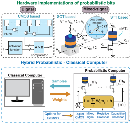
The image presents a diagram illustrating hardware implementations of probabilistic bits, categorized into Digital and Mixed-Signal approaches, and a depiction of a Hybrid Probabilistic-Classical Computer architecture. The diagram details the components and flow of signals within each implementation.
### Components/Axes
The diagram is divided into two main sections: "Hardware implementations of probabilistic bits" (top) and "Hybrid Probabilistic - Classical Computer" (bottom).
**Top Section:**
* **Digital (CMOS based):** Includes components like PRNG, activation function, comparator (A > B), and logic gates (NAND, NOR).
* **Mixed-Signal:** Contains SOT based and STT based implementations.
* **SOT based:** Shows a spin-orbit torque device with voltage sources (V⁺ = VDD / 2 + VR, V⁻ = VDD / 2), resistor (R₀), and output voltage (VOUT).
* **STT based:** Depicts a spin-transfer torque device with a magnetic barrier, voltage sources (VDD), and output voltage (VOUT).
* Labels: VIN, VOUT, VR, VDD, KT, Eb, Δ, m.
**Bottom Section:**
* **Classical Computer:** Depicted as a desktop computer tower.
* **Probabilistic Computer:** Shows multiple probabilistic bit devices (m1...mN) connected to summation and activation functions.
* Equation: {I} = Σ wᵢmᵢ + hᵢ
* Options for synapse: Digital, Mixed signal, Resistive Crossbar, Capacitive Crossbar.
* Labels: Samples, Weights.
### Detailed Analysis or Content Details
**Top Section - Digital (CMOS based):**
* A Pseudo-Random Number Generator (PRNG) feeds into a series of NAND and NOR gates.
* The output of the logic gates goes through an activation function.
* The activation function output is compared using a comparator (A > B).
* The comparator output is indicated by an arrow.
**Top Section - Mixed-Signal (SOT based):**
* A cylindrical device with blue and orange layers is shown.
* Voltage sources V⁺ and V⁻ are connected to the device.
* A resistor R₀ is connected to the device.
* An output voltage VOUT is indicated.
* The diagram shows a low barrier magnet with energy Eb and Δ ≤ 0 KT.
**Top Section - Mixed-Signal (STT based):**
* A cylindrical device with blue and orange layers is shown, labeled as sMTJ.
* Voltage source VDD is connected to the device.
* An output voltage VOUT is indicated.
* The diagram shows a low barrier magnet.
**Bottom Section - Hybrid Probabilistic-Classical Computer:**
* A bidirectional arrow labeled "Samples" connects the Classical Computer to the Probabilistic Computer.
* A bidirectional arrow labeled "Weights" connects the Classical Computer to the Probabilistic Computer.
* The Probabilistic Computer consists of multiple probabilistic bits (m1 to mN) connected to summation and activation functions.
* The equation {I} = Σ wᵢmᵢ + hᵢ represents the computation within the probabilistic computer.
* The "Options for synapse" section lists Digital, Mixed signal, Resistive Crossbar, and Capacitive Crossbar.
### Key Observations
* The diagram illustrates different approaches to implementing probabilistic bits, ranging from traditional digital CMOS circuits to more novel mixed-signal devices based on spin-orbit torque (SOT) and spin-transfer torque (STT).
* The hybrid architecture suggests a combination of classical and probabilistic computation, leveraging the strengths of both paradigms.
* The equation provided indicates a weighted sum of probabilistic bits followed by an activation function.
* The "Options for synapse" section highlights potential hardware implementations for the connections between probabilistic bits.
### Interpretation
The diagram demonstrates a conceptual framework for building probabilistic computers, potentially offering advantages in areas like machine learning and optimization. The use of both digital and mixed-signal implementations suggests a flexible approach to hardware design. The hybrid architecture allows for leveraging existing classical computing infrastructure while incorporating the benefits of probabilistic computation. The different synapse options indicate ongoing research into the most efficient and effective ways to connect and process probabilistic bits. The inclusion of the equation {I} = Σ wᵢmᵢ + hᵢ suggests a neural network-inspired approach to probabilistic computation, where the probabilistic bits act as neurons and the weights represent synaptic strengths. The diagram is a high-level overview and does not provide specific details about the performance or scalability of these implementations. It is a conceptual illustration of potential architectures rather than a detailed engineering blueprint.