TECHNICAL ASSET FINGERPRINT
c6533350f07f77e65837ca86
Click to view fullscreen
Press ESC or click to close
FOUND IN PAPERS
EXPERT: healer-alpha-free VERSION 1
RUNTIME: free/openrouter/healer-alpha
INTEL_VERIFIED
## Diagram: Hardware Implementations of Probabilistic Bits and Hybrid System
### Overview
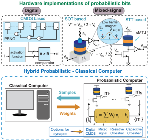
The image is a technical diagram illustrating two main concepts: 1) Three distinct hardware implementation approaches for probabilistic bits (p-bits) at the top, and 2) A conceptual architecture for a Hybrid Probabilistic-Classical Computer at the bottom. The diagram uses circuit schematics, block diagrams, and labels to explain the components and data flow.
### Components/Axes
The diagram is divided into two primary sections by a horizontal dashed line.
**Top Section: Hardware implementations of probabilistic bits**
This section is further divided into three columns, each representing a different implementation strategy.
1. **Left Column (Digital):**
* **Header Label:** "Digital"
* **Sub-header Label:** "CMOS based"
* **Components:** A block diagram showing a chain of logic gates (D flip-flops and XOR gates) labeled "PRNG" (Pseudo-Random Number Generator). This feeds into a block labeled "activation function," which connects to a comparator block labeled "A > B" with an output labeled "m".
2. **Middle Column (Mixed-signal):**
* **Header Label:** "Mixed-signal"
* **Sub-header Label:** "SOT based"
* **Components:** A schematic of a Spin-Orbit Torque (SOT) device. It features a cylindrical "Low barrier magnet" with annotations: "E_b" (energy barrier), "Δ ≈ 0 kT" (indicating near-zero thermal stability), and an angle "θ". The magnet is connected to a circuit with a resistor "R_0", a transistor, and voltage inputs/outputs labeled "V_IN", "V_OUT", "I_s", and equations "V⁺ = V_DD / 2 + V_R" and "V⁻ = V_DD / 2".
3. **Right Column (Mixed-signal):**
* **Header Label:** "Mixed-signal"
* **Sub-header Label:** "STT based"
* **Components:** A schematic of a Spin-Transfer Torque (STT) device. It shows a "sMTJ" (spin-transfer torque magnetic tunnel junction) connected to a circuit with a transistor and voltage labels "V_DD", "V_IN", and "V_OUT".
**Bottom Section: Hybrid Probabilistic - Classical Computer**
* **Main Header Label:** "Hybrid Probabilistic - Classical Computer"
* **Left Side:** An icon of a desktop computer labeled "Classical Computer".
* **Right Side:** A block labeled "Probabilistic Computer". Inside this block:
* A row of p-bit symbols (a magnet icon over a transistor) labeled "m₁" through "m_N".
* A central summation block with the equation: "I_i = Σ_j W_{ij} m_j + h_i".
* Input arrows labeled "{I_i}" and output arrows labeled "{m_i}".
* **Data Flow:** Two large arrows connect the computers:
* A blue arrow pointing left labeled "Samples".
* An orange arrow pointing right labeled "Weights".
* **Footer Element:** A box labeled "Options for synapse" with an arrow pointing to four listed implementation types: "Digital CMOS", "Mixed signal", "Resistive Crossbar", "Capacitive Crossbar".
### Detailed Analysis
* **Digital Implementation (CMOS based):** This is a purely digital circuit. A PRNG generates random bits, which are processed by an activation function and compared against a value (B) to produce the probabilistic output bit (m).
* **Mixed-signal Implementations (SOT & STT based):** These are analog/magnetic implementations. Both use a magnetic element (low-barrier magnet or sMTJ) whose state is influenced by input currents/voltages. The SOT design explicitly shows the magnet has a near-zero energy barrier (Δ ≈ 0 kT), making its state easily fluctuating and thus probabilistic. The output voltage (V_OUT) is a function of the magnetic state.
* **Hybrid System Architecture:** The diagram proposes a system where a classical computer exchanges data with a probabilistic computer. The classical unit sends "Weights" (likely for a neural network or probabilistic model) to the probabilistic unit. The probabilistic unit, composed of many p-bits (m₁...m_N) performing a summation operation (I_i = Σ W_{ij} m_j + h_i), generates "Samples" which are sent back to the classical computer. This suggests an iterative inference or learning loop.
* **Synapse Options:** The diagram notes that the synaptic connections (the "W" in the equation) within the probabilistic computer can be implemented using various technologies: Digital CMOS, Mixed-signal, Resistive Crossbar (like memristors), or Capacitive Crossbar.
### Key Observations
1. **Technology Spectrum:** The diagram presents a spectrum from fully digital (CMOS) to mixed-signal (SOT/STT) hardware for p-bits, highlighting different trade-offs in design.
2. **Core Probabilistic Element:** The mixed-signal implementations rely on nanomagnetic devices with intentionally low thermal stability to achieve inherent probabilistic behavior, unlike the digital approach which uses algorithmic randomness (PRNG).
3. **System-Level Integration:** The bottom half shifts focus from individual p-bit components to a system-level view, emphasizing the symbiotic relationship between deterministic classical processing and probabilistic sampling hardware.
4. **Modular Synapse Design:** The "Options for synapse" box indicates that the critical weight-storage component in the probabilistic computer is modular and can be built with different emerging memory technologies.
### Interpretation
This diagram serves as a conceptual roadmap for building probabilistic computing hardware. It argues that p-bits can be physically realized through different mechanisms—from conventional digital circuits to novel spintronic devices—and that these p-bits are not standalone but are most powerful when integrated into a hybrid architecture.
The **data flow** (Samples ← Classical → Weights) suggests a use case like Bayesian inference or training of probabilistic neural networks. The classical computer handles precise calculations and model management (weights), while the probabilistic computer efficiently generates stochastic samples from the model defined by those weights. The equation `I_i = Σ_j W_{ij} m_j + h_i` is characteristic of a Boltzmann machine or a similar energy-based model, where `I_i` is an input current to p-bit `i`, `W_{ij}` are connection weights, `m_j` are the states of other p-bits, and `h_i` is a bias.
The inclusion of multiple synapse technologies (Resistive/Capacitive Crossbar) points toward a hardware-efficient implementation where the weight matrix `W` could be stored in a crossbar array, performing the summation operation in-place using analog physics (Ohm's law and Kirchhoff's current law), which is a key advantage of mixed-signal and neuromorphic computing paradigms. Overall, the image advocates for a heterogeneous computing approach where specialized probabilistic hardware accelerates tasks that are inherently random or uncertain, working in tandem with classical systems.
DECODING INTELLIGENCE...