## 3D Conceptual Diagram: Unit-Case Relationship
### Overview
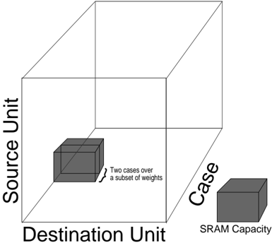
The image is a black-and-white line drawing of a three-dimensional cube diagram. It visually represents a conceptual relationship between three primary dimensions: "Source Unit," "Destination Unit," and "Case." Within this conceptual space, two smaller cubes are depicted to illustrate specific subsets or constraints. The diagram appears to be a technical illustration, likely from a paper or presentation on computing architecture, memory systems, or data processing, explaining how computational cases relate to hardware resources.
### Components/Axes
The diagram consists of a large, transparent wireframe cube defining a 3D coordinate space. The three axes of this space are labeled as follows:
* **Vertical Axis (Y-axis):** Labeled **"Source Unit"**. The text is oriented vertically along the left edge of the cube.
* **Horizontal Axis (X-axis):** Labeled **"Destination Unit"**. The text is oriented horizontally along the bottom front edge of the cube.
* **Depth Axis (Z-axis):** Labeled **"Case"**. The text is oriented diagonally along the bottom right edge, receding into the background.
Inside and outside this main cube are two smaller, solid gray cubes:
1. **Internal Cube:** A smaller, shaded cube is positioned inside the main cube, near the origin (bottom-left-front corner). An arrow points to it with an accompanying text annotation.
2. **External Cube:** A second, similarly sized shaded cube is positioned outside and to the right of the main cube, near the "Case" axis label.
### Detailed Analysis
* **Text Annotation:** The text annotation pointing to the internal cube reads: **"Two cases over a subset of weights"**. This text is in English.
* **Internal Cube Position & Meaning:** The internal cube is located at the intersection of low values on the "Source Unit" and "Destination Unit" axes and spans a portion of the "Case" axis. Its placement and the annotation suggest it represents a specific, limited operational scenario—a subset of possible computational "cases" that operate on a defined "subset of weights."
* **External Cube Label:** The external cube is labeled directly below it with the text **"SRAM Capacity"**. This label is in English.
* **External Cube Position & Meaning:** This cube is placed outside the main conceptual space defined by the three axes. Its separation and distinct label indicate it represents a separate, physical constraint or resource (Static Random-Access Memory capacity) that is external to the logical problem space defined by Source Unit, Destination Unit, and Case.
### Key Observations
1. **Conceptual vs. Physical:** The diagram creates a clear distinction between the logical problem space (the large cube defined by Source, Destination, and Case) and a physical hardware limitation (SRAM Capacity).
2. **Subset Representation:** The internal cube is a visual metaphor for a specific, bounded instance within the larger problem domain. The phrase "Two cases over a subset of weights" implies a focused analysis or workload.
3. **Spatial Grounding:** The "SRAM Capacity" cube is deliberately placed outside the main cube, emphasizing that memory capacity is a constraint that exists independently of the logical dimensions of the problem but must be considered alongside them.
4. **Visual Hierarchy:** The use of a wireframe for the main cube and solid shading for the smaller cubes effectively draws attention to the specific instances (the subset and the constraint) within the broader conceptual framework.
### Interpretation
This diagram is a conceptual model illustrating the interaction between a computational workload and hardware resources. The large cube represents the full problem space: any operation can be defined by its source, its destination, and the specific case (or scenario) being executed.
The key insight is the relationship between the two smaller cubes. The internal cube ("Two cases over a subset of weights") represents a specific, manageable portion of the total computational problem. The external cube ("SRAM Capacity") represents the finite physical memory available to store the data (weights) and intermediate results for those cases.
The diagram suggests that for a given hardware configuration with fixed SRAM capacity, only certain subsets of the total problem space (certain combinations of Source Unit, Destination Unit, and Case) can be executed at one time. The workload must be partitioned or scheduled such that the active "cases over a subset of weights" fits within the available "SRAM Capacity." It visually argues that understanding and optimizing this fit—mapping logical problem subsets to physical resource constraints—is critical for system performance. The absence of numerical data indicates this is a high-level, architectural concept diagram rather than a quantitative chart.